Obtaining parts
All the parts could be obtained from Digikey or Mouser, the BOM has part numbers for both. Most are jellybean parts so you can surely get them from other sources.
Newhaven NHD-0208BZ-FL-YBW LCD specified in the BOM is readily available from both Digikey and Mouser and works nicely, however it requires substantial back light current (70mA!) and black-on-green is the only color available. It also lacks back light contacts on the main LCD header, so one needs to add two more pins at the right side of the LCD to provide power for back light.
Personally I prefer ERM802-3 series LCDs from BuyDisplay (available on ebay and directly from http://www.buydisplay.com), their white-on-black, white-on-blue and black-on-yellow models look great and require only 15mA for back light. The connector header is 8×2 and has back light pins configuration compatible with MidiGAL PCB, so there is no need to add A/K pins on the right side of the LCD.
Preparing for the build
If you’re new to soldering, please check these tutorials before proceeding — they are super helpful:
- EEVblog #180 – Soldering Tutorial Part 1 – Tools
- EEVblog #183 – Soldering Tutorial Part 2 – Through hole soldering
The commonly accepted strategy for populating printed circuit boards is to add low profile components first (resistors, diodes, anything else axial), then proceed with higher profile parts (ceramic capacitors, IC sockets, etc), then finish with highest-profile components (electrolytic capacitors, connectors, etc).
It’s also a good idea to wash the board a few times during the build: this allows you to better inspect solder joints quality and keep those microscopic solder whiskers away.
So let’s get started… take your time, no rush, and enjoy the build!
Component side assembly
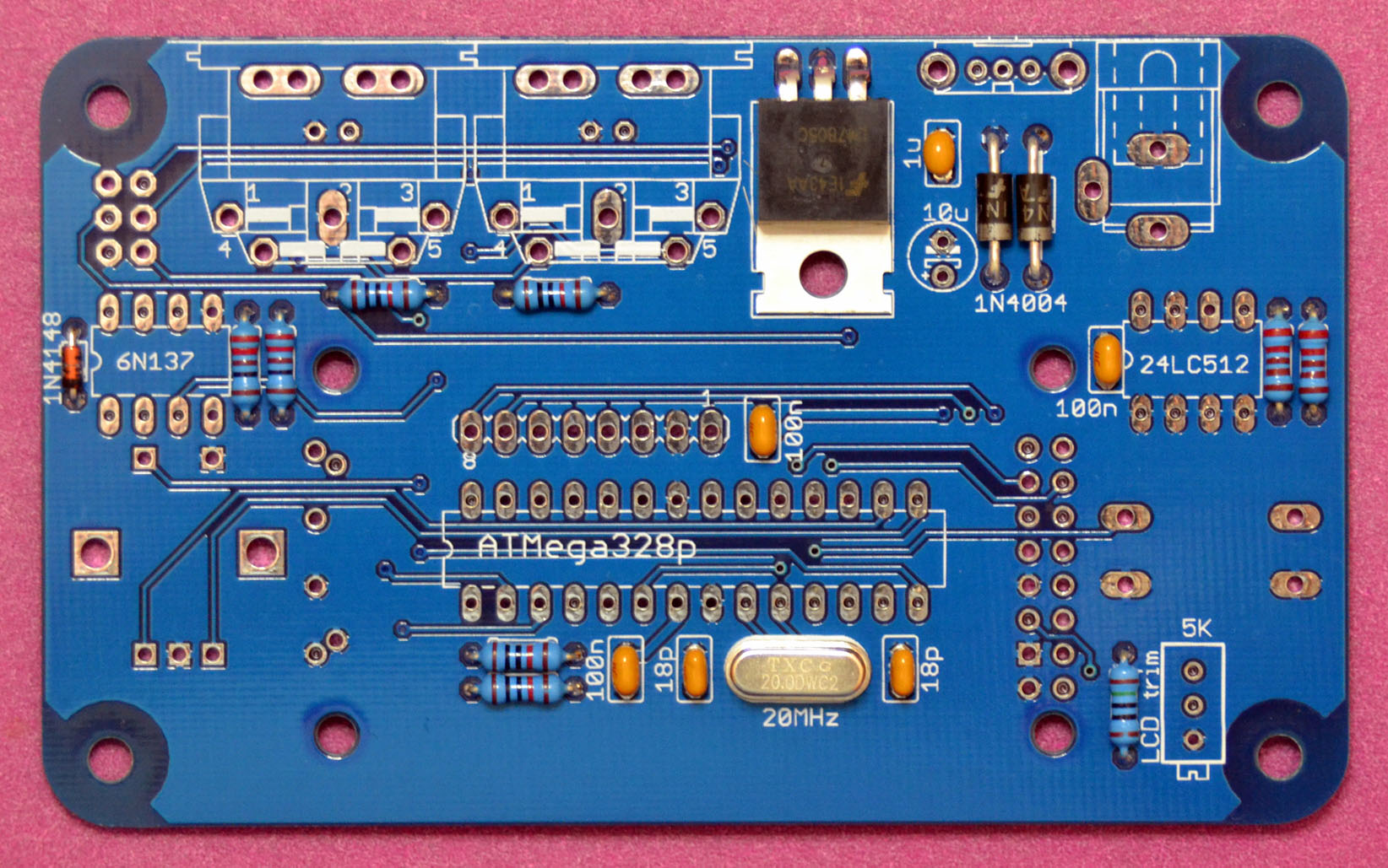
The bare PCB de-greased with isopropyl alcohol:

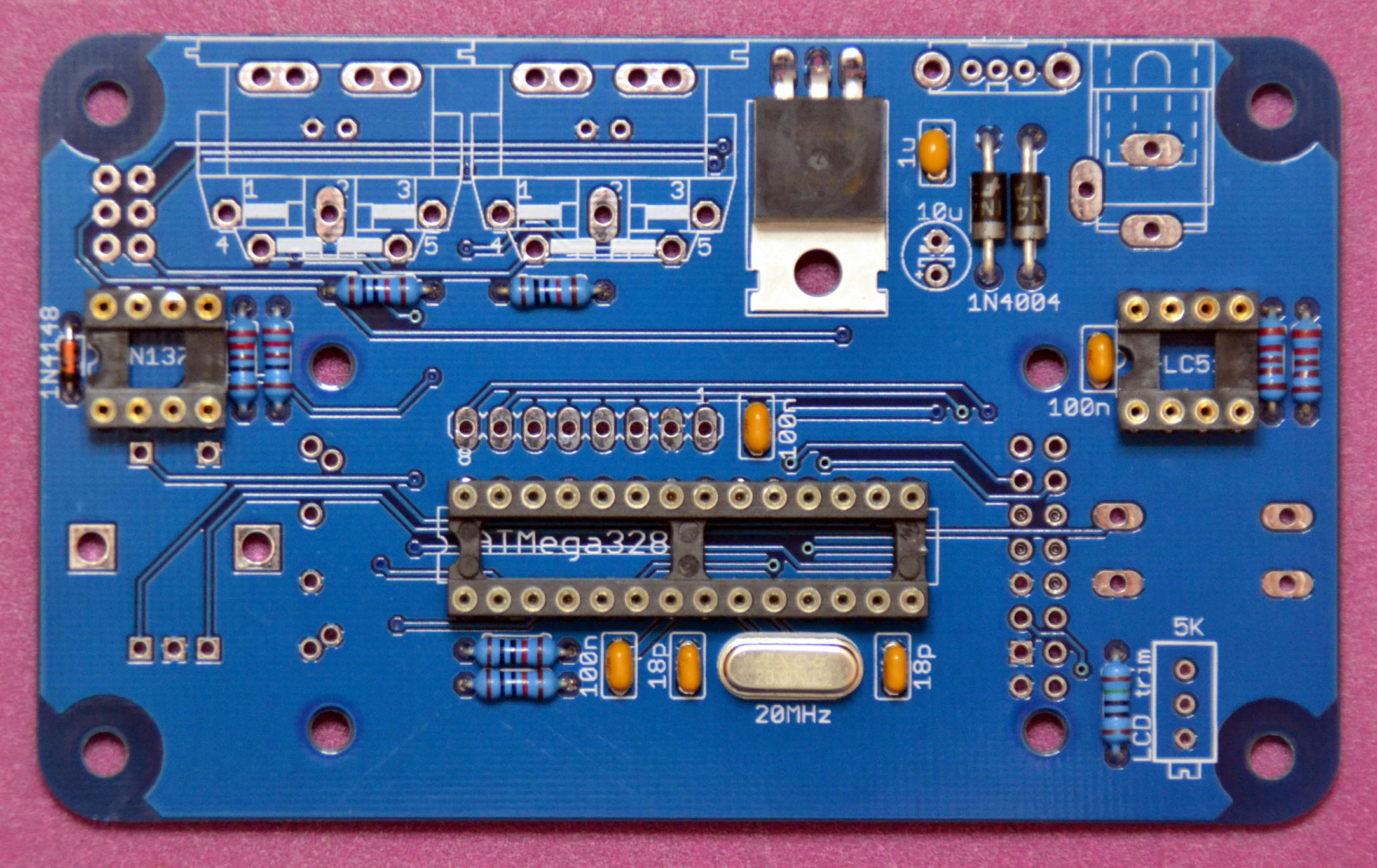
Add resistors:
- 2 x 220 Ohm
- 2 x 2.2K
- 4 x 10K
If you’re going to use low intensity green or red LEDs replace 10K current limiting resistors (red arrows) with 220Ohm resistors, in which case you will install:
- 4 x 220 Ohm
- 2 x 2.2K
- 2 x 10K
Add LCD back light current limiting resistor (green arrow). This one is 3 Ohm for Newhaven NHD-0208BZ-FL-YBW LCD specified in the BOM, or 150 Ohm for preferred ERM802-3 series LCD from BuyDisplay available on eBay. Please review your LCD specification to find out the correct back light current limiting resistor value!

Add diodes:
- 1 x 1N4148 (red arrow)
- 2 x 1N4004 (green arrow)
Diodes are polarity sensitive, so please make sure you install them correctly: line near the cathode pin should match the line on the silk screen legend.

Add ceramic capacitors:
- 3 x 0.1uF
- 2 x 18pF (red arrows)
- 1 x 1uF (green arrow)

Add LM7805 voltage regulator and a 20MHz quartz:
Add IC sockets paying attention to the orientation: the notch should be on the left!.
- 2 x 8 pin
- 1 x 28 pin
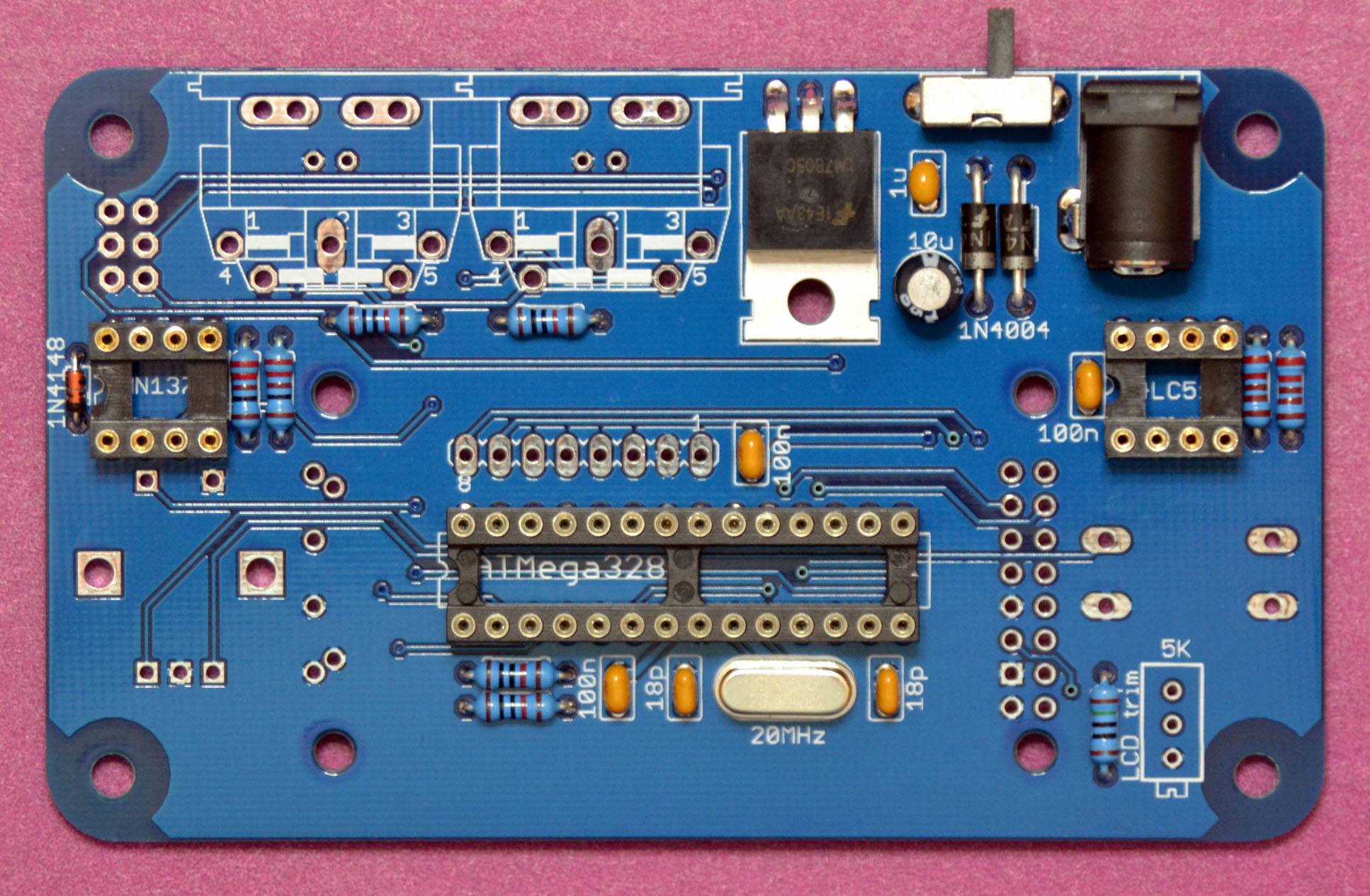
Add 10uF 25V electrolytic capacitor:

Add 2.1mm DC connector and power switch:
Add 8×1 extension header (optional) and 5K LCD contrast trim pot:

Add 2 x MIDI connectors:

Bottom side assembly is done. Turn the board upside down and trim solder joints to keep them nice and tidy:

Top side assembly
Add AVR ISP Programmer connector 3×2 header if you’re planning to use flash programmer. If you don’t know what it is, skip this step.

Add tactile switch and encoder:

Add 2 x MIDI LEDs. These are polarity sensitive, so make sure long leg (anode) goes to the left!

MIDI LEDs are soldered from the top because by now bottom is covered by MIDI connectors. Note that installing MIDI LEDs before you mount MIDI LEDs is not a good idea since you will have to file LED’s solder joints perfectly flush to the PCB, risking to damage it. Soldering LEDs from top turns out to be much easier.

Preliminary testing
At this point the only component left to be installed is LCD. Installing the LCD will cover some important solder joints (MCU pins), so it’s recommended to verify the core functionality before proceeding.
Use your DMM to verify the following:
- Test connectivity between all the green points (GND)
- Test connectivity between all the red points (VCC)
- Test no connectivity between any green and red point (no power rail short)

If the above checks out fine, connect 9VDC power adapter (center pin positive!), move the power switch to the position closest to the DC switch and use your DMM to verify presence of the +5V voltage between any green and red point. It won’t be exactly 5V in most cases, anything between 4.8 and 5.2V is good.
If you’re have pre-programmed ATMega328p MCU it’s time to install it. Pay attention to the IC’s orientation: the notch should go to the left.
If you are flashing MCU yourself, it’s time to do it. Fuse settings: low=FF, high=D4, extended=FD.

Install 6N137 optocoupler IC (left) and optional external EEPROM IC (right). Pay attention to the IC’s orientation: the notch should go to the left!

At this point you can perform a “blind” test of the device functionality without the LCD.
If you’re running MidiClk firmware, verify the following:
- LEDs should simultaneously blink a few times after the device is powered up
- if you power the device up holding down the encoder, LEDs should blink a few times alternately (firmware update mode)
- if you power the device up holding down the switch, the device should switch Clock Tester mode to Clock Generator mode, or back
- connect a MIDI controller to MIDI IN and sounds source to MIDI OUT, then verify that MIDI passes through and LEDs blink
If you’re running MIDIpal firmware, verify the following:
- if you power the device up holding down the encoder, LEDs should blink a few times alternately (firmware update mode)
- make sure MIDI events are passed through from MIDI IN to MIDI OUT and LEDs blink accordingly
If everything checks out correctly, you are safe to proceed. If something does not work as expected, the device may be not in a mode you think it is. In this case, it’s better to proceed and get LCD working without soldering it in, see below.
LCD installation
Add electrical tape to protect LCD from coming into contact with PCB solder joints:

Solder 8×2 pin header to LCD panel. If the LCD you’re using has only 7×2 pins, cut the extra two from the header:

At this point it is recommended to temporarily install the LCD and check if it is working.
Important: most of the time you won’t see any characters until the LCD contrast is adjusted using LCD Trim pot. You may have to rotate it up to 20 times before characters are visible. Start turning the pot CW first and switch to CCW after you turn it 20 times, or when you start hearing distinctive “click” every time you turn it.

Install the LCD:

Done!

Newbie question: when you say “If you’re going to use low intensity green or red LEDs…”, do you mean to say that ALL green and red LEDs are low intensity, or some (green and red) LEDs are low intensity? The LEDs in the current BOM (digikey: 1080-1115-ND) require 10k or 2.2k resistors? Thanks!
Some newer green and red LEDs are actually high intensity. The ones in the BOM are high intensity. However, to be on the safe side, you may want to postpone soldering these resistors until after the thing is built and try different resistors to you taste or working conditions.
Thanks, that’s very helpful!
More newbie questions! For the 8×1 extension header, should the longer pins point up or down? Should the solder side pins be trimmed? Also, the 10uF 25V electrolytic capacitor: is it polarized? Seems like it’s not polarized, but the PCB shows a +ve pad; just making sure… Thanks!
8×1 extension is soldered from the component side, short pins to the PCB, and trimmed on the opposite side of the PCB since it is under LCD.
Electrolytic caps are polarized, so make sure it is installed correctly.
Is there any reason one couldn’t add a 9V battery connector, as there is on the MIDIpal? I know MIDIpal has a specific place for it, is there a spot one could be soldered on the midiGAL?
MidiGAL does not have dedicated pads for a battery connector like MIDIpal does, however you can still add it by soldering a wire to the unused pin of the power switch and ground.
I’ve gotten to the point of testing the LCD. Turning on the unit with the encoder depressed, I do get the in/out LED’s flashing alternately (MIDIPal firmware). I’ve soldered the 8×2 connector to the LCD, and inserted it into the PCB (having placed an insulator below). I adjust the contrast trim, and I eventually get one (just one) row of 8 rectangles (covering roughly half the screen), each composed of 8×5 pixels. I’ve wiggled the LCD assembly around; sometimes the rectangles disappear, but I never get more than that (no proper characters, nothing on the LCD’s other half). I’ve tried turning the unit off/on, still nothing. Could it just be that I am not making proper contact with all 16 pins, and that there is no problem really (in which case, should I just solder the LCD to the PCB)? Or do you think there is a problem?
Also, do you have a Digi-key part number for those 4 nylon (?) posts that support the LCD?
Thanks!
LCD is initialized as part of the boot up sequence, so it is important to have the good contact at the time the unit is powered up. I usually solder in header to the LCD, then insert and push it up a little, then switch the unit on. If it does not work, switch off and on again. It usually works after a few tries.
I buy nylon screws from a local parts shop, don’t know where to get them online, but they are just regular 4.40 nylon screws and nuts.
Thanks. Tried turning on/off dozens of times, still only rectangles… Do you have any suggestions for next steps?
Hello esteban, hello Kvitekp, I finish to mount the midigal and hapens the same, only one row in the display and no words on it.
Could be the display or could be the atmega thats is not ok, thanks in advance.
Enrique.
Chances are it’s connection between MCU and LCD.
I have the exact same problem. Two separate PCBs, two separate LCDs. Both display only one row of black rectangles. I soldered one of the LCD headers to the PCB to make sure the connection is solid. Neither works. One of the LCDs displayed text for about 15 sec before turning back to the rectangles. Troubleshooting?
Boxes in the top row mean that LCD controller does not receive initialization info. There may be a lot of reasons for that. One reason is MCU not working at all, this could be eliminated if LED are blinking upon power on. If MCU is working , it could hang before initializing LCD, this often happens if something is wrong with external EEPROM which gets set up before LCD. Alternatively, one of six LCD control lines could be broken or shorted.
Leaving this in case anyone has this problem. I fixed this issue by:
a) re-flashing the mcu via sysex with the midipal_gal firmware
AND
b) turning the trimpot ccw to reduce contrast. The white blocks were hiding the letters. Basically, I thought seeing the white blocks was good but actually you want the pot somewhere in the middle.
That said, I’m not sure which of those things actually fixed the device, but the lcd screen is populating for me now.
The trim pot is there to set the LCD contrast. You must set the trim pot to the position specific to your LCD.
MidiGAL built successfully. Yay! Is it possible to switch firmwares between MidiPAL, MidiALF and MidiSeq using the sysex method?
Congrats! Sure, see firmware update instructions in downloadable firmware files here: https://midisizer.com/midigal/#diy
Hello Peter I have problems with my midigal, whe i connect the display, only one row works.
I check all connections, it seems are ok, I power up while hold down the encoder and the leds blink how you say, and starts update mode. I send midi to midigal and detects.
The display is from buydisplay and the model is ERM802SBS-3, I put another new one (the same model), and makes the same, only one row.
What do you think, could be the display (model not compatible).
Thanks in advance an sorry for my english.
Enrique.
Hi Enrique — i’m using exactly the same LCD from teh same supplier and it works great. The LCD initialization is done when the unit powers up, so it is important that LCD header has a good contact on all pins when you test it.
Hey peter,
I’ve gotten to testing stage but couldn’t find a barrel jack for mounting on the pcb. Do I need to fill all of the through holes to complete the circuit or am I missing something else? I’ve tried attaching a 9v battery to my leads and I’m not getting any activity on the board.
Does that make sense? Thanks!
You don’t need to fill the holes. Just connect the negative wire to the pad in the middle of the connector, and the positive wire to the pad at the end opposite to where the jack goes, then move the power switch to the position closest to the power connector. That should do it.
Hi Pete, is it possible to use a regular 2×16 LCD instead of 1×8 ? Thx a lot.
yes, if you don’t mount it on the PCB
Hi Pete, sorry but I could not find where to buy MidiGAL PCB and price. Thank you!
It’s at the bottom of MidiGAL page: https://midisizer.com/midigal/#ordering
Dear Pete, I assembled MidiGal on a breadboard this weekend. I uploaded Midipal and MidiClk and everything worked nice. When I uploaded MidiArp and MidiSeq, nothing happened, just an empty LCD. I´ve been using a 2×16 LCD and a 24LC128 eeprom. Do you think that 2×16 LCD and/or 24LV128 eeprom could be a problem to MidiGal hardware ? Thank you !
I just uploaded MidiArp and MidiSeq firmware to MidiBUD, which is essential MidiGAL with 16×2 LCD and four more switches, and they work perfectly fine, including display.
EEPROM size is certainly not a problem, the unit can run without EEPROM, you just won’t be able to save programs, however all other functionality will work the same.
After you upload new firmware, it’s a good idea to initialize the unit by powering it up while holding down the switch.
Hello Pete, i just startet to build your MidiGal by setting the Fuses at a m328p (Atmega 328p -PU) on a breadbord but something went wrong?!
Im using an ArduinoUno as ISP and connect the target as shown here (internal clock-mode):
(bottom-left-corner configuration) https://www.arduino.cc/en/Tutorial/ArduinoToBreadboard
Then i first READ the fuses of a fresh m328p and avrdude says: lfuse 62; hfuse D9 and efuse 7.
After reading i went to the webside http://www.engbedded.com/fusecalc to check your values and it gives me a note that the extendet fuse containing undefined bits.
It says its better to change the efuse to 0x05 instead of 0xFD.
btw, its my first contact with “fuseing”.. but nevermind… try&error 😀
than i write the fuses with avrdude with your numbers (FF; D4; FD) and the MCU was bricked!! ^^
(fyi: i send the values at a speed of 19200 baud – is this to fast?)
finaly i managed it to ‘repair’ the MCU by supporting an external clock at XTAL1 by 1MHz and was able to set the default-values back into the fuses *pew* ..the MCU works well again 😀
so now i’m a bit confused…
was it my fault to start without an external clock (yours is a 20MHz crystal) and i just use the internal 8MHz?
And is it possible to use a 16MHz crystal (for breadbording) instead your 20MHz, because i dont have the right one at the moment? 😉
thx for your response and help
and a big thumbs up for your work 🙂
-303otto
(oh and sry for this wall of text)
You have to start with external 20MHz xtal if you use MidiGAL fuse settings — they explicitly specify external xtal. Using 16MHz is not a good idea because the code is compiled for 20Mhz clock frequency and using a different clock frequency will screw up delays and communication protocols. To calculate fuse settings I use Atmel’s own Atmel Studio which is presumed to give correct fuse word values.
ah i see, ok 🙂
something like that was swirling around my head by thinking about the specific 20MHz XTAL.
Thank you very much for your response!
Keep up your awesome work, m8! 🙂
Hello Pete,
do i have to burn the midipal_eeprom.hex even when i just want to use the midiseq-firmware?
I have installed the eeprom-IC on the board and in the menu i can scroll thru 64 saveslots instead of the discribed 32 slots – does this mean, the eeprom is burned correctly and used by the firmware? (btw, i have burned the midipal_eeprom.hex after the midiseq.hex onto the MCU – just want to verify that i have done all the correct way)
Thank you and best regards 🙂
-otto
no you don’t, midipal_eeprom.hex is only needed for MIDIpal firmware.
MidiSeq firmware figures out the installed eeprom size and calculates number of available save slots automatically. You’ve probably installed the larger EEPROM IC.
I’m having a very strange issue! I’m using ATMEGA328’s, not 328P’s (for the most part – keep reading) and have successfully burned and run the Clock, Arp and Seq. They all work great. However, when I tried burning the Midipal (gal version) hex / eeprom, First the EEPROM won’t burn – no worries, I’ll just get a 328p. The eeprom (and main hex) burned in just fine on the 328p with my SKT500, but the LCD just has the row of filled bars at the top. I did set the fuses exactly the same as the seq, clock and arp, and in fact have burned in the arp, used it, burned in the midipal, noted that it didn’t work, then reburned the arp then clock and both the arp and clock work just fine.
So, I’ve tried it on both the 328 (no eeprom) and 328p (appears to be great, but doesn’t work).
I think I must misunderstand the basic idea of how the loader works, and now I think I’m getting the impression you just have to upload the bootloader, then chuck the sysex at the board (with 250ms delays etc) and swap out the functionality that way as opposed to burning multiple chips. No worries. SO, then I uploaded the midipal hex, flashed the eeprom (328p) and turned it on while holding down the encoder. The lights do the correct sequence, however, when sending sysex at the board, the in/out lights do not light at all, even though midi-ox is sending and the USB-> midi adapter’s OUT light is blinking at the appropriate rate with the 250ms pauses.
I also tried uploading the original midipal golden hex, and had the exact same issue.
I’m at a loss! it FEELS like I’m missing something with the fuses (confirmed they are correct soooo many times). I don’t think the lock bit is an issue, or shouldn’t be. I’ve inspected the board with my usb microscope looking for bizarre trace cuts or shorts that might only show up with some midipal specific pin access, but can’t find anything.
I’m at a loss here, and I’d sincerely appreciate any help you can give me!
MidiArp/Seq/Clk and MIDIpal use slightly different boot loaders and sysex files. The logic is the same, but the expected manufacturer id is different. MIDIpal uses MI’s manufacturer id, whereas MidiArp/Seq/Clk use borrowed PPG id. If you want to update firmware on MIDIpal flashed MCU, you need to send sysex files with _pal suffix and vise versa.
I appreciate the response – I’ll see what I can do on it. I flashed it every which way I could, I believe, but couldn’t find any luck. I’ll keep at it!
I am having the same problem when trying to upload firmware via sysex. I’m using _pal version with midipal bootloader. Boot midigal into firmware update mode, midi in LED is lit. When I start sysex transfer the LED goes off and does not blink. Nothing is transferred. Any insight is appreciated.
Could it be that you actualy have the alternate bootloader?
MIDIpal bootloader flashes leds 3 times with 100ms interval, whereas alternate bootloader uses 250ms interval.
Hey, I tried both sets of firmware with both delay timings and the midi in led goes off when I start the transfer and does not blink at all. I got the MCU from you programmed with the midipal firmware. In monitor mode midigal (with midipal) shows that sysex is being sent and midi in led blinks. I am using a generic usb host to midi cable. I suppose its possible that is faulty but I don’t think so. I’ve tried midiox,C6 and a few other sysex utlities.
I bought an avr isp programmer and am just gonna try to upload it that way. What is the process? Do I need to proceed as if I am flashing from scratch or can I just send the new firmware over? Thanks!
Hi, I’m facing a similar issue, the LEDs go blank when sending the sysex messages with the firmware update (MidiSeq). I think I might have bricked it, forgot to specify 250ms delay between messages in the first sysex update run. I can still access the firmware update mode however, but not on every boot-up I try. Other than occasionally reaching the update mode, where sysex update fails, I only get the blank screen when powering on.
Any ideas will be much appreciated!
(I got a preprogrammed chip, so I guess it’s not related to the MidiPAL/MidiGAL bootloader issue.)
Martin, there was a broken MidiSEQ firmware sysex v1.01 available online for a short period of time. Please try any other firmware variant or download MidiSeq f/w v1.02 https://midisizer.files.wordpress.com/2021/10/midiseq_102.zip
Thanks for the reply @kvitekp, I just used the file linked on https://midisizer.com/midigal/midiseq-sequencer/, it seems it’s still there.
However with your new version, I still have the same issue, booting to update mode seems OK, when I start to send sysex messages, the left LED turns off and nothing happens. There is only the blank screen. Tried with the MidiArp firmware as well, same result.
It seems similar to https://midisizer.com/midigal/comment-page-2/#comment-19175. Will email you separately.
I’ve updated the link to point to 1.02 f/w — https://midisizer.files.wordpress.com/2021/10/midiseq_102.zip
I have been trying to find a device (not a computer) that would work as a master MIDI clock for my outboard MIDI gear. Would this work?
Yep, this is exactly what MidiClk firmware for MidiGAL was designed for. If you have many device to clock from MidiGAL it is recommended to split MidiGAL output into 5 identical parallel MIDI streams with MidiThru.
Hello Pete,
I’m building the MidiGal but when testing it before installing the LCD only one of LEDs flashes on startup, the left one MIDI In. I’ve checked solder points but no luck. Any ideas why this might be happening?
Thanks!
If one LED is blinking, the processor is working, so the problem is with the other LED line solder joints. You’ll need to check connectivity and shorts on the othe LED line.
To confirm before I destroy my midiGAL, can I use a 12V power source for this instead of 9V? It looks like the voltage regulator in the BOM specifies max 35V, so I think it should be OK to use based on what you said about 5V USB supply in the midiREX comments, but I don’t really know.
Yeah, 12V should be OK … just keep an eye on your voltage reg and if it gets too hot, switch it off. It will get hot if your LCD draws a lot of current.
Hey!
1. Can I still order one of these built and shipped to FL, USA?
2. I just need some type of basic arpeggiator for my DX7 that at least can do repeat notes and set tempo for such. MidiGAL can do that right?
Sure you can. Please email me at the address specified on the ordering page here: https://midisizer.com/midigal#ordering
MidiGAL with MidiARP firmware will certainly do all the basic arpeggiator things and a few more cool arp related tricks.
I’m not sure if my original comment posted so I apologize if I’m double posting.
Am I still able to buy one of these pre-built with an acrylic case?
Additionally, could I create a single note repeat with it? Or is another one of your creations a better device for that sort of thing? (here’s a song for reference of what I mean: https://www.youtube.com/watch?v=cZvt23iBVVo)
Thanks!
Yup, MidiARP can do it easily.
Hi Pete!
As I will not receive my encoder from mouser before the end of March, do you think I can replace it with the model used in MidiRex? I ordered 2 of them.
PS: MidiRex is really cool!!
Yes you can, however MidiREX encoder has a shorter shaft, so if you plan to put your MidiGAL into enclosure, you have to make sure that the encoder knob will fit into the opening. Acrylic cases i’m providing allow you to use narrow skirt knob that fits the short encoder.
Thanks!
Will do that very soon!
Hum hum…
I’m currently making my Midigal and I realize that I did not ordered the 10uF 25V electrolytic capacitor….
Can I replace it by a 10uF 16v or a 10uF 50v?
a 10uF 50v will do it. Dont take the weaker 16v one!
Thanks @otto ! I really have to learn about capacitors
Me again 🙂
I’m having troubles flashing midipal firmware.
Here are the commands I typed:
Fuses:
avrdude -c usbtiny -p atmega328p -U lfuse:w:0xFF:m -U hfuse:w:0xD4:m -U efuse:w:0xFD:m
This one is ok
Boot:
avrdude -c usbtiny -p atmega328p -U flash:w:muboot.hex
Seems OK too
Midipal:
avrdude -c usbtiny -p atmega328p -U flash:w:midipal.hex
If I stop here, pushing the encoder while starting do nothing
eeprom:
avrdude -c usbtiny -p atmega328p -U eeprom:w:midipal_eeprom.hex
Lot of errors. The upload seems to be 1024 Bytes and the eeprom is 512?
OK. So when flashing the Midipal Hex I specified -D option to upload without erasing flash then uploaded eeprom hex.
Still some errors while uploading eeprom.
The test seems to be ok
avrdude -c usbtiny -p atmega328p -U lfuse:w:0xFF:m -U hfuse:w:0xD4:m -U efuse:w:0xFD:m
avrdude -c usbtiny -p atmega328p -U flash:w:muboot.hex
avrdude -c usbtiny -p atmega328p -D -U flash:w:midipal.hex
avrdude -c usbtiny -p atmega328p -U eeprom:w:midipal_eeprom.hex
avrdude: error: usbtiny_send: error sending control message: Connection timed out (expected 128, got -110)
avrdude: error: usbtiny_receive: error sending control message: Protocol error (expected 4, got -71)
avrdude: error: usbtiny_receive: error sending control message: Protocol error (expected 4, got -71)
*** Error in `avrdude’: munmap_chunk(): invalid pointer: 0x000000000205baa0 ***
I tried with the screen without soldering it and I have only black rectangles …
Now it’s partially working. I explain:
The midipal eeprom flash issue is due to a bug in avrdude linux (64 bits?)
So I did flash MidiArp firmware with success.
Now I can update via sysex but only with Midiox on windows 7 (virtualbox) and changing buffer to 250ms.
Midipal or Midipal_gal still don’t work. When I end Midipal_gal sysex, the 2 les are blinking and finally the screen stay black.
If someone have a trick to install Midipal firmware…
I stop geeking now and go playing with MidiArp!
Jeremy, read thru this page to find a solution for your upload/flash-problem: https://www.sequencer.de/synthesizer/viewtopic.php?t=107574
Thanks otto, will try to translate that!
Hey Jeremy, Have you figured out the problem? I tried flashing the firmware using the commands you posted and I’ve having the black rectangles issues. MCU seems to boot fine since the LEDs are blinking and I’ve tried also updating the firmware via sysex with no success.
Is your trim pot adjusted properly so that the letters on the lcd screen will show up? if it’s one way too far, nothing will show up and if it’s the other way too far, you just get black rectangles.
I should have specified I only see black rectangles on the first row and nothing on the second row. I have tried turning the pots until it clicked both CW and CCW but nothing really changes
Hi – on one MidiSeq build I did today the rotary encoder won’t menu select when depressed. All other functions seem OK (clock send, scroll through menu, power up tests etc). Guess I’ll reflow the pin joints to see if that fixes it..but out of interest which pin route (A, B or C) should I troubleshoot if that fails? The other MidiSeq and MidiArip I built today work great !! Thanks for some great work Peter !
If encoder click is not detected, you need to check continuity between encoder pin that is closest to the board edge and opto-coupler and MCU pin 14.
If continuity is present, try to short this signal to ground and see if this works as a click and if so, replace the encoder. Don’t try to desolder it, just cut the legs as high as possible and desolder them one by one.
Also replied via email.
Problem sorted…continuity was present, shorting to ground did work as a click and so I reflowed the solder joint to the encoder pin and BINGO… I then remembered that when I’d pushed the knob onto the encoder shaft I’d heard a “click” but had dismissed it. Perhaps I pushed on the pot too hard and a weak joint gave way. Anyway, happy boy now and grateful for such prompt, specific support from you. Really helps when DIY’ing. Thanks again !
Great!
Hi. Can someone make one MidiGAL for me or sell it in Moscow?
Sure, fully assembled MidiGAL in acrylic case is $145 plus $25 shipping to Europe. Please email me at the address specified on the ordering page if you are interested.
Midigal received, all is working perfectly, just bought a standarD 0802 display, backlight pins are on the right side…
Thankz a lot !
Congrats on the successful build!
I’m facing a strange problem. Firstly I tried the firmwares for midiseq, midiarp and midiclk and they are correctly working, the device seems to display the correct informations on the screen. Then I tried flashing midipal.hex and midipal_eeprom.hex with USBasp and avrdude: the report seems correct with the device correctly programmed. Finally, when i power up the device i can see only the top row filled with black rectangles. At this point the only action that seems to move something is pushing the encoder, by doing this the first row shows chn[all] and it’s also possible to change this parameter. I can get no access to other parameters and functions. Any idea ?
MIDIpal firmware has different LCD update dynamics, so LCD trim needs to be adjusted. Try to load MidiSEQ or ARP and verify encoder rotate/click operation.
Thanks, I already checked with midiseq and the encoder works fine. However, even if i can visualize chan[all], it’s not normal that the midipal starts-up with black rectangles. (Contrast trimpot works fine because i can read chan[all] when i press the encoder).
Ok, it was my fault, now it’s working! Thank for all.
How much is an assembled MidiGAL without case, shipped to Denmark?
$120 plus $25 shipping to EU
Hi, i have my midigal for a long time, but no enclosure. Is it possible that you provide the stl files for the 3d print case? Or is there any chance to buy just a case?
Please email me at the address specified on the ordering page. Thank you!