MidiThru x2 is an easy build that usually takes between one and two hours for an average builder. This is not a speed contest though, so take your time and build at the pace you are comfortable with.
All the parts could be obtained from Digikey or Mouser, the BOM has part numbers for both. Most are jellybean parts so you can surely get them from other sources.
If you’re new to soldering, please check these tutorials before proceeding — they are super helpful:
- EEVblog #180 – Soldering Tutorial Part 1 – tools.
- EEVblog #183 – Soldering Tutorial Part 2 – through hole soldering.
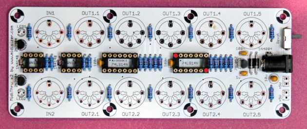
As usual, start with low profile components first.
Install 6 x 10K resistors:
Install 22 x 221R resistors: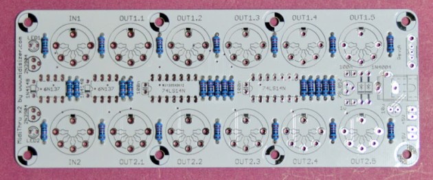
Install 2 x 1N4148 and 2 x 1N4004 diodes. Note that these components are polarized, so make sure the strip position matches the silkscreen legend:
Install 3 x 100nF and 1uF ceramic capacitors: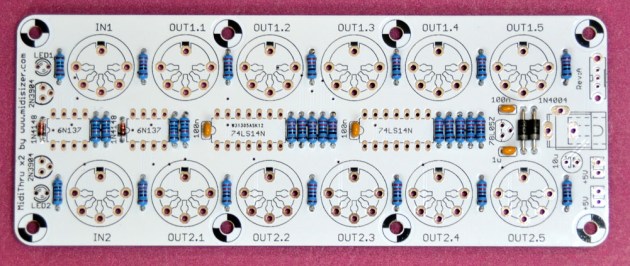
Install 10uF tantalum capacitor. Note that this component is polarized, so make sure the long leg goes into the hole marked with plus sign:
Install 2 x DIP8 and 2 x DIP14 IC sockets. Make sure that the notch is on the left side: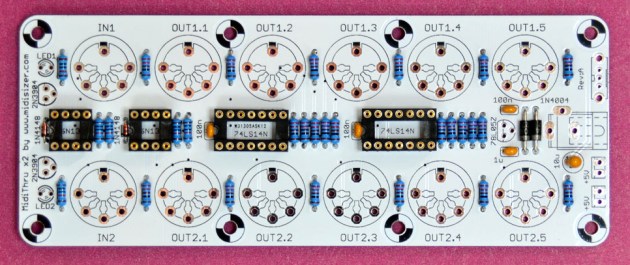
Install 2 x 2N3904 transistors and 78L05 voltage regulator. The flat side should match the silk screen legend:
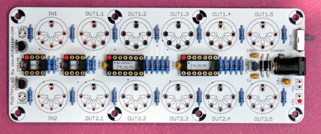
Install DC jack and power switch:
Time to do some checks!
Verify continuity between GND pins: pin 7 of DIP14 IC socets, pin 5 of DIP8 IC sockets and power supply ground (red dots):
Verify continuity between VCC pins: pin 14 of DIP14 IC socets, pin 8 of DIP8 IC sockets and power supply output (red dots):
Verify discontinuity between GND and VCC pins (pin 7 and 14 of any DIP14 socket):
If the above checks out correctly, plug in 9VDC 2.1mm center positive power supply, switch on the power by moving DC switch towards the DC connector and check for +5V DC between GND and VCC pins (pin 7 and 14 of any DIP14 socket):
If the above checks out, you’re good to proceed with the rest of the build.
IMPORTANT! Some DIN5 connectors have outer diameter slightly larger than others which makes it difficult to remove the top panel after DIN5 connectors are installed. Please check if your DIN5 connectors freely go through the top panel holes and if not, install the ICs now so you don’t have to remove the top panel later.
Attach 14mm stand offs (you may need to add a 0.8mm washer for perfect vertical alignment with DIN5 connectors):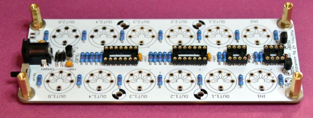
Temporarily mount top panel: it will serve as a guide for installing connectors and LEDs:
Install 12 x DIN5 connectors, carefully aligning them to the top panel, then remove it:
Install 2 x 6N137 optocouplers and 2 x 74HC14 Hex Smidtt trigger ICs: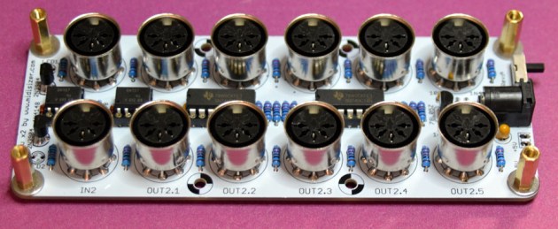
Install 2 x LEDs adjusting the leg height so that LED lenses raise above the top panel by 1mm. To achieve this, the distance between LED plastic bottom and the top of the PCB should be 13mm:
Optional: Rev.A PCBs have two optional MTA02-100 headers which are connected to power rails GND and VCC so you can have up to 5 MidiThru x2 devices powered from the same power supply. If you are building such a configuration please omit power supply components from the slave devices.
Install the top panel back: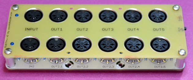
You are done! Now connect MIDI cable to MIDI input connectors and verify MidiThru x 2 operation: LEDs should blink and MIDI events should pass through.
Don’t forget to celebrate the successful build!
