Obtaining parts
All the parts could be obtained from Digikey or Mouser, the BOM has part numbers for both. Most are jellybean parts so you can surely get them from other sources.
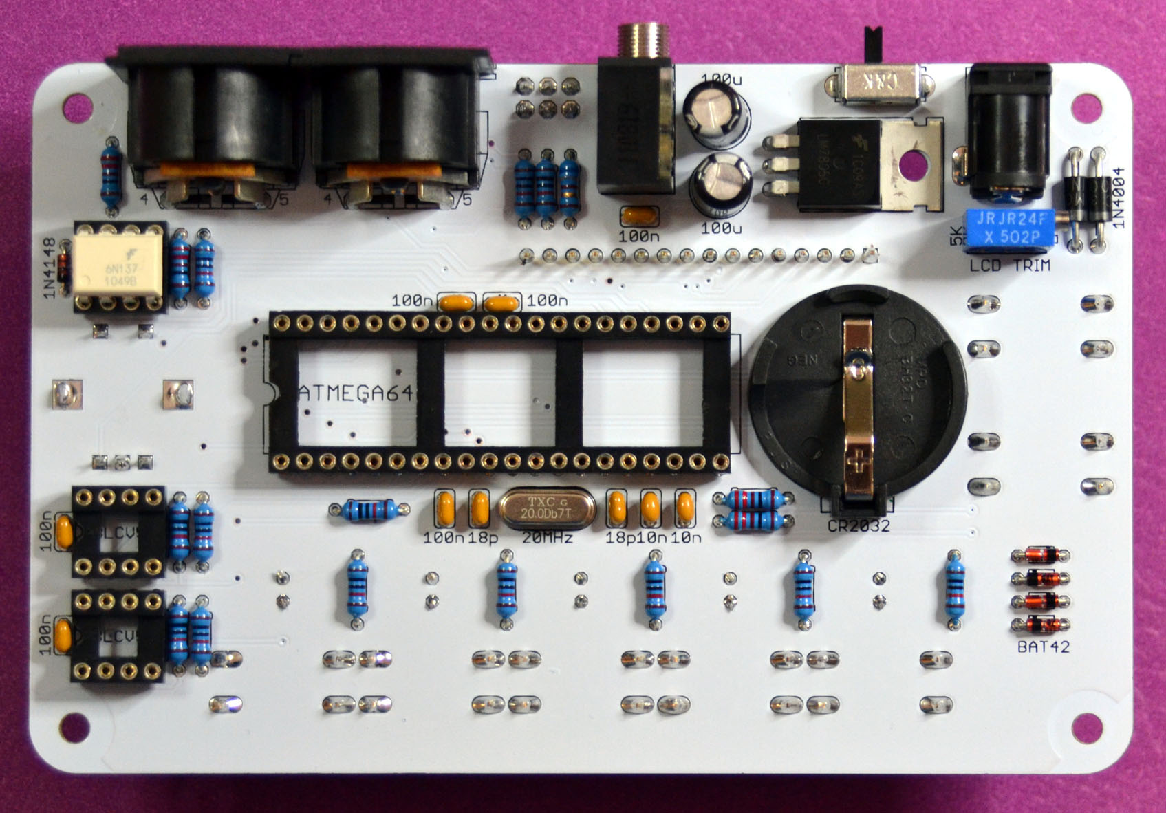
Component side assembly
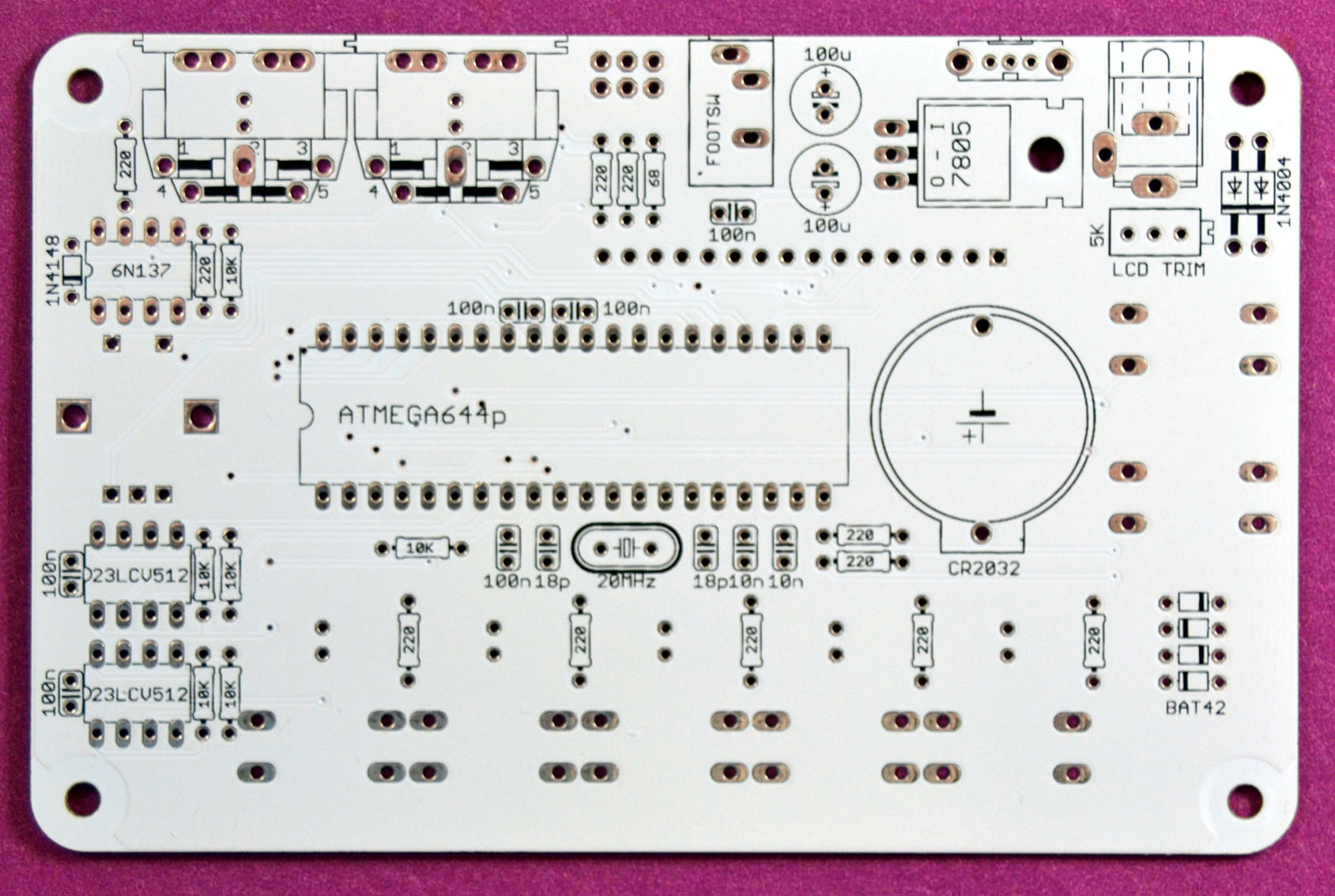
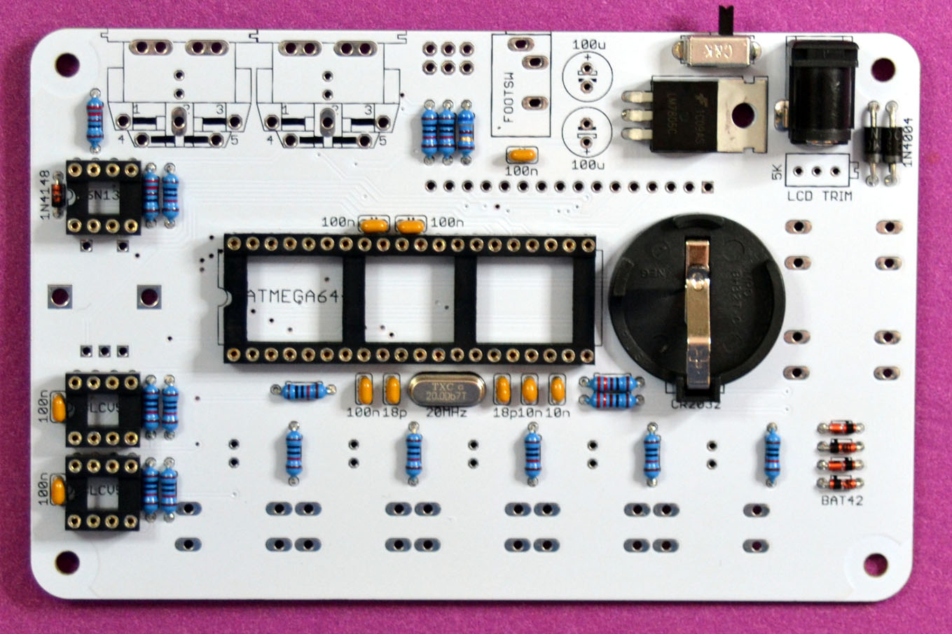
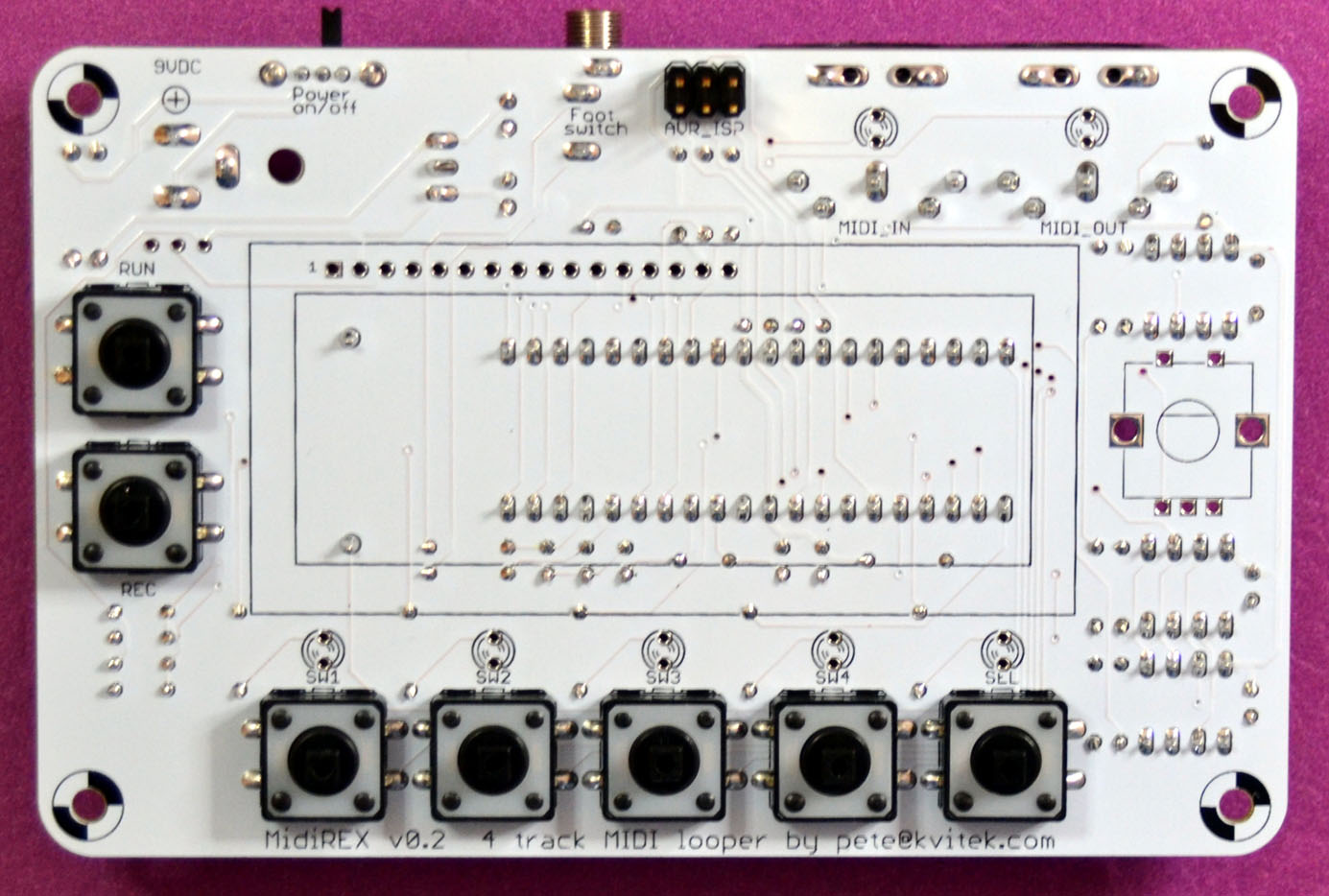
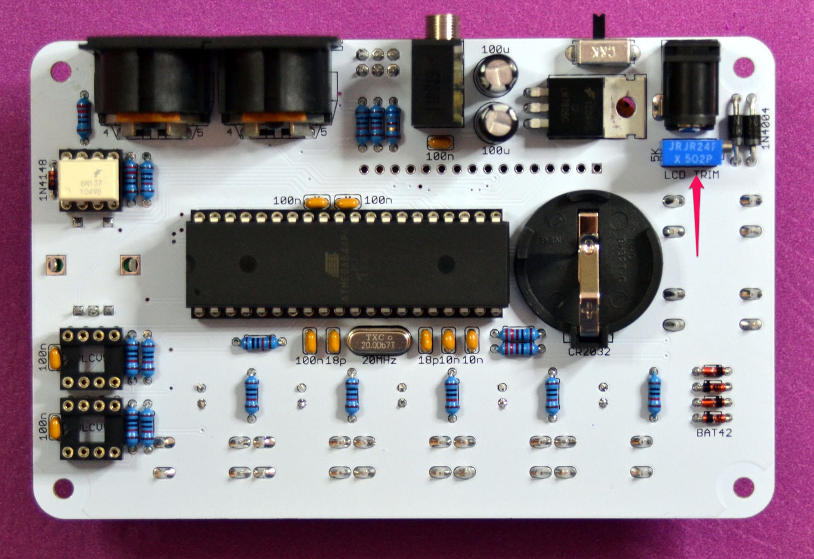
The bare PCB de-greased with isopropyl alcohol:
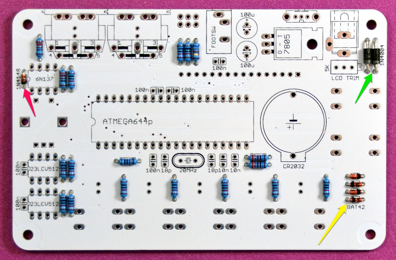
Add resistors:
- 11 x 220 Ohm
- 6 x 10K
- 1 x 68 Ohm
If you’re going to use high intensity blue or white LEDs replace 220 Ohm current limiting resistors (red arrows) with 10K resistors, in which case you will install:
- 13 x 10K
- 4 x 220 Ohm

Add diodes:
- 1 x 1N4148 (red arrow)
- 2 x 1N4004 (green arrow)
- 4 x BAT42 (yellow arrow)
Diodes are polarity sensitive, so please make sure you install them correctly: line near the cathode pin should match the line on the silk screen legend.
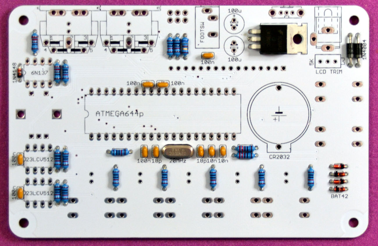
Add ceramic capacitors:
- 6 x 0.1uF
- 2 x 18pF (red arrows)
- 2 x 10nF (green arrow)

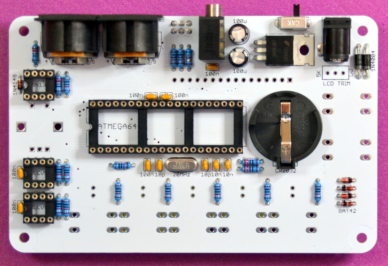
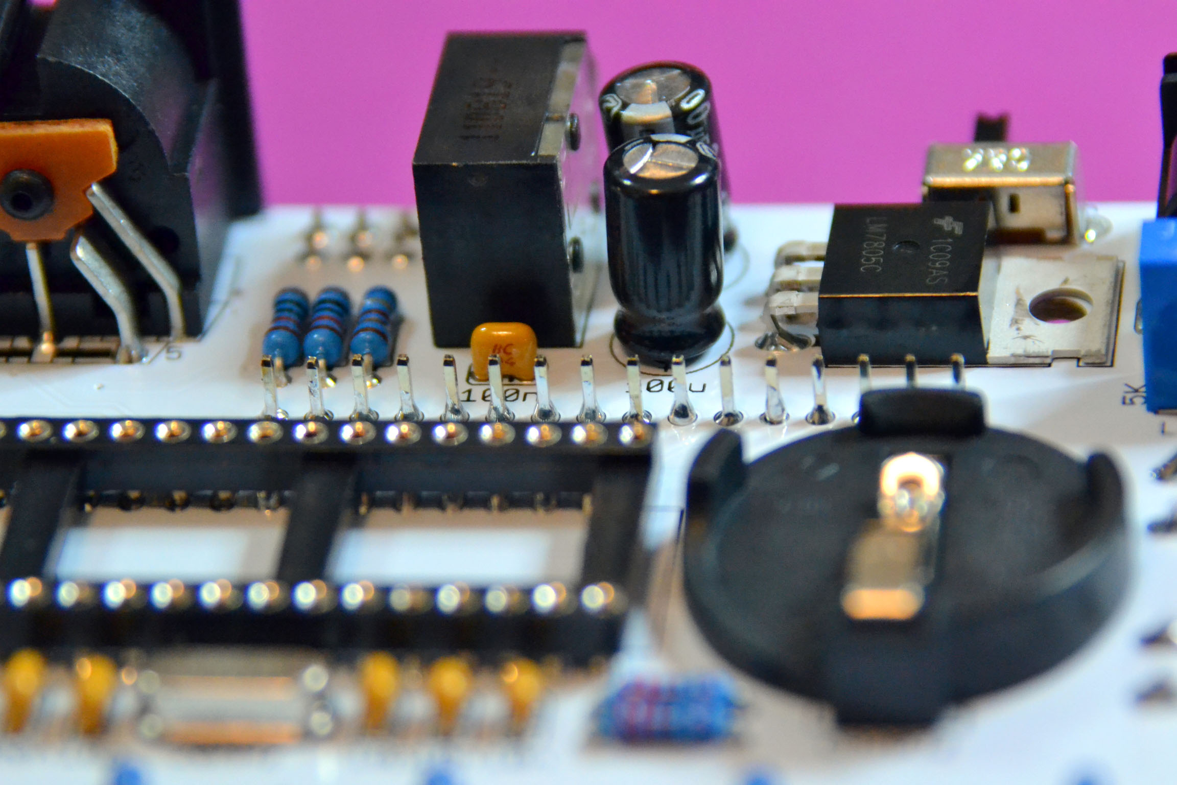
Add LM7805 and a 20MHz quartz:
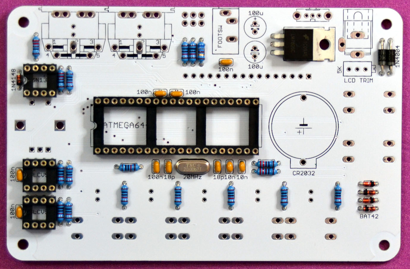
Add IC sockets.
- 3 x 8 pin
- 1 x 40 pin
Please make sure the notch is on the left!
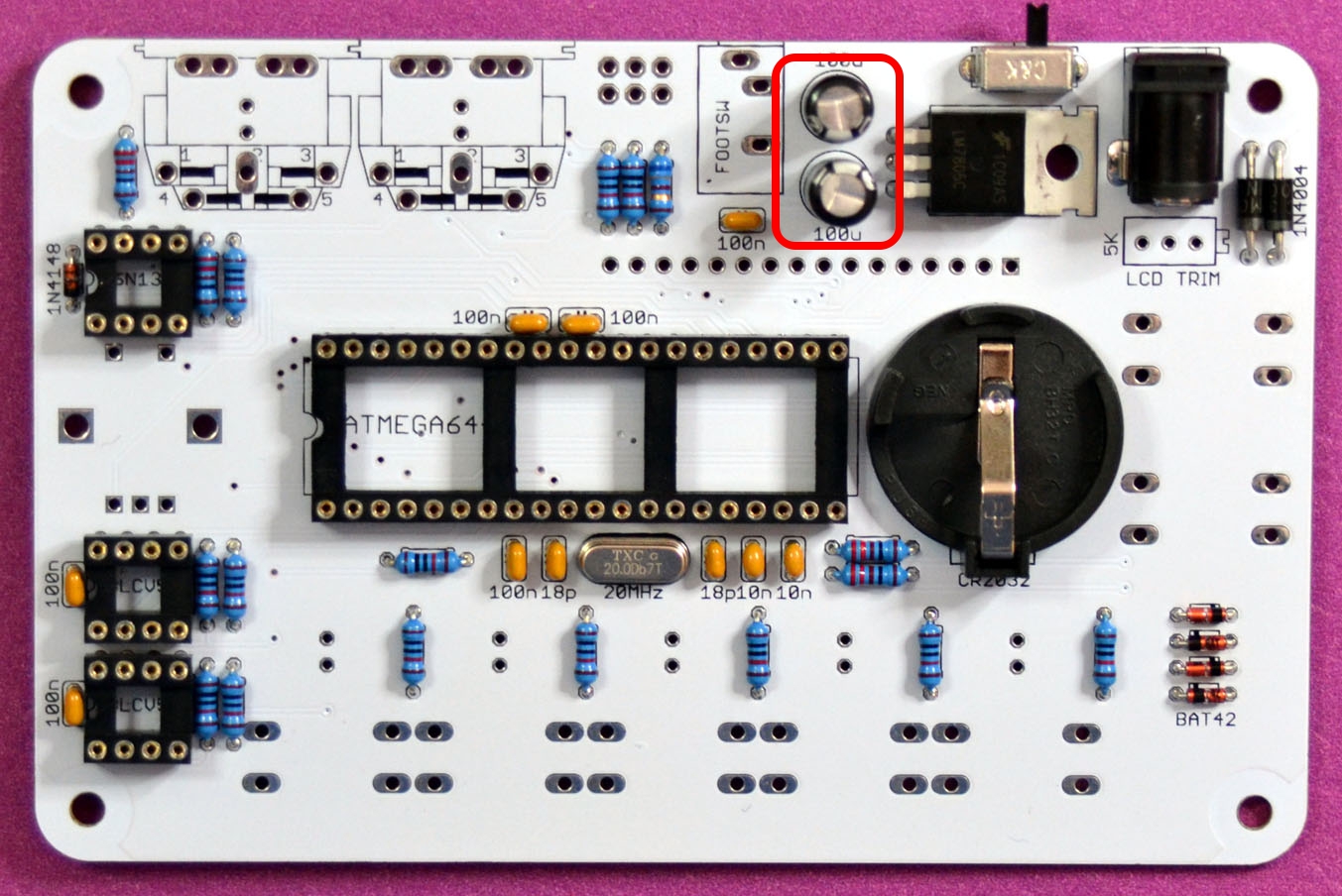
Add 2.1mm DC connector. power switch and battery holder:
Add 2 x 100u 16V electrolytic capacitors. These are polarity sensitive, please make sure the longer leg (positive terminal) goes into the + pad.
Flip the board and install 3×2 pin header for AVR ISP connector. You may skip this if you are not planning to use AVR ISP programmer to program MidiREX’es MCU.
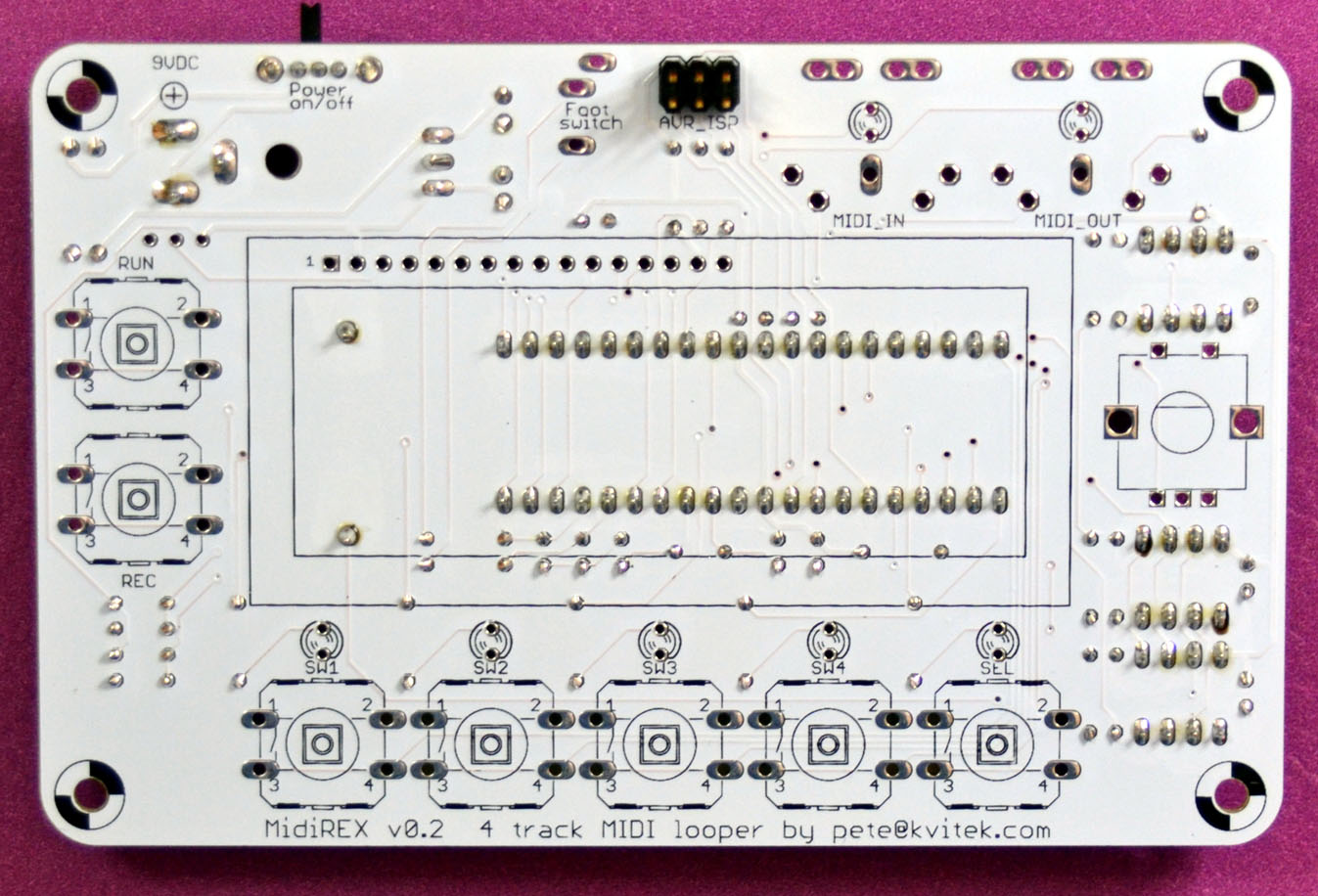
Add 2 x MIDI connectors and 3.5mm foots witch jack connector:
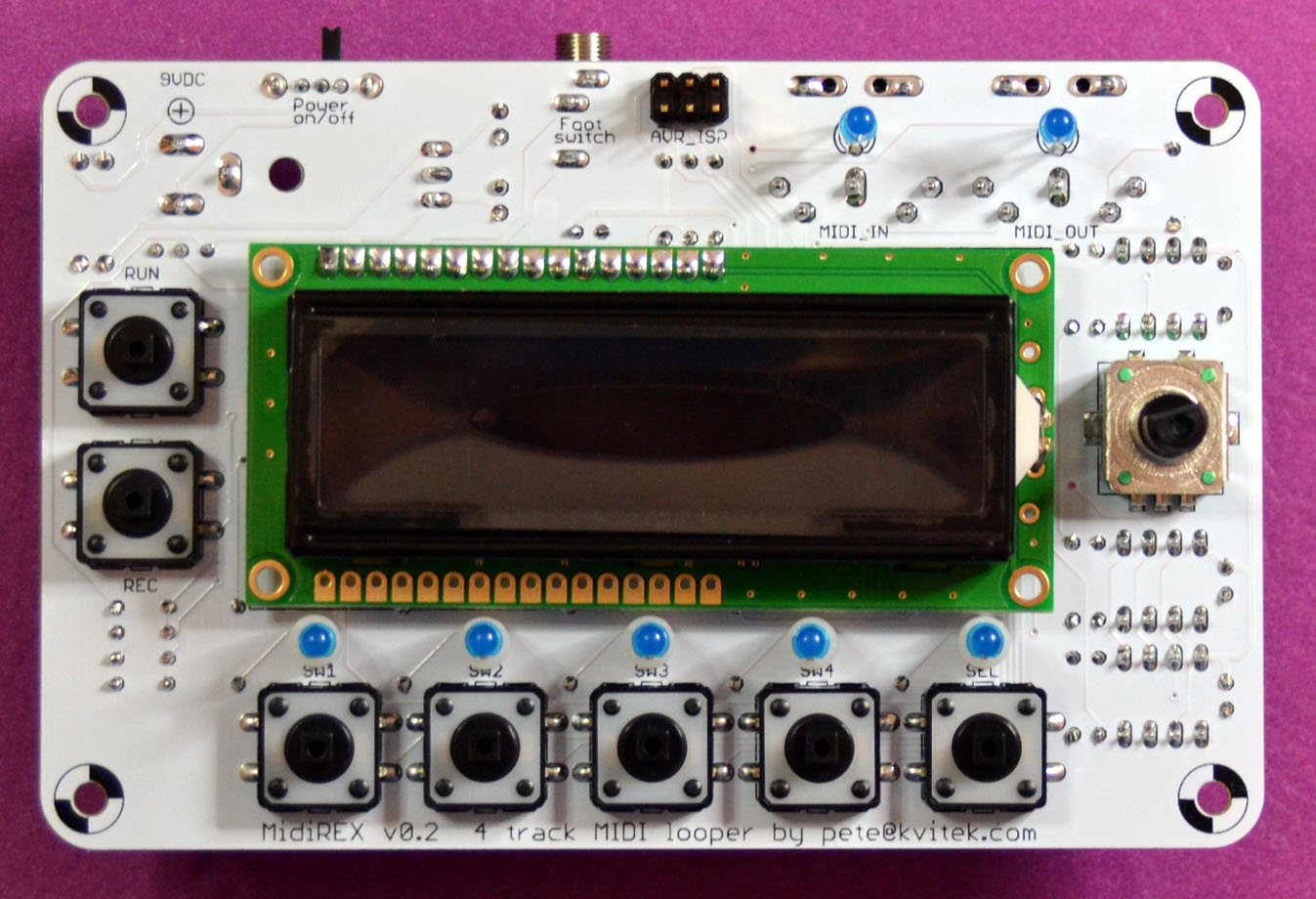
Top side assembly
Add 7 x tactile switches:
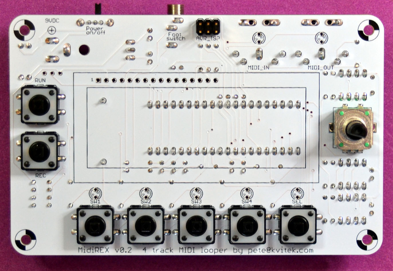
Add encoder:
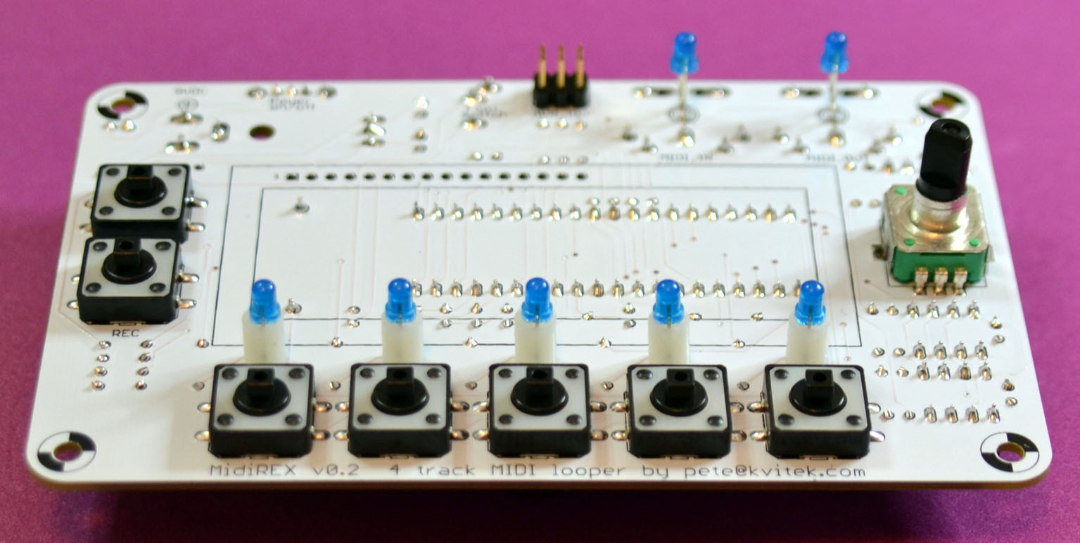
Add 5 x switch LEDs with 0.3″ spacers and 2 x MIDI LEDs. These are polarity sensitive, so make sure long leg (anode) goes to the top!
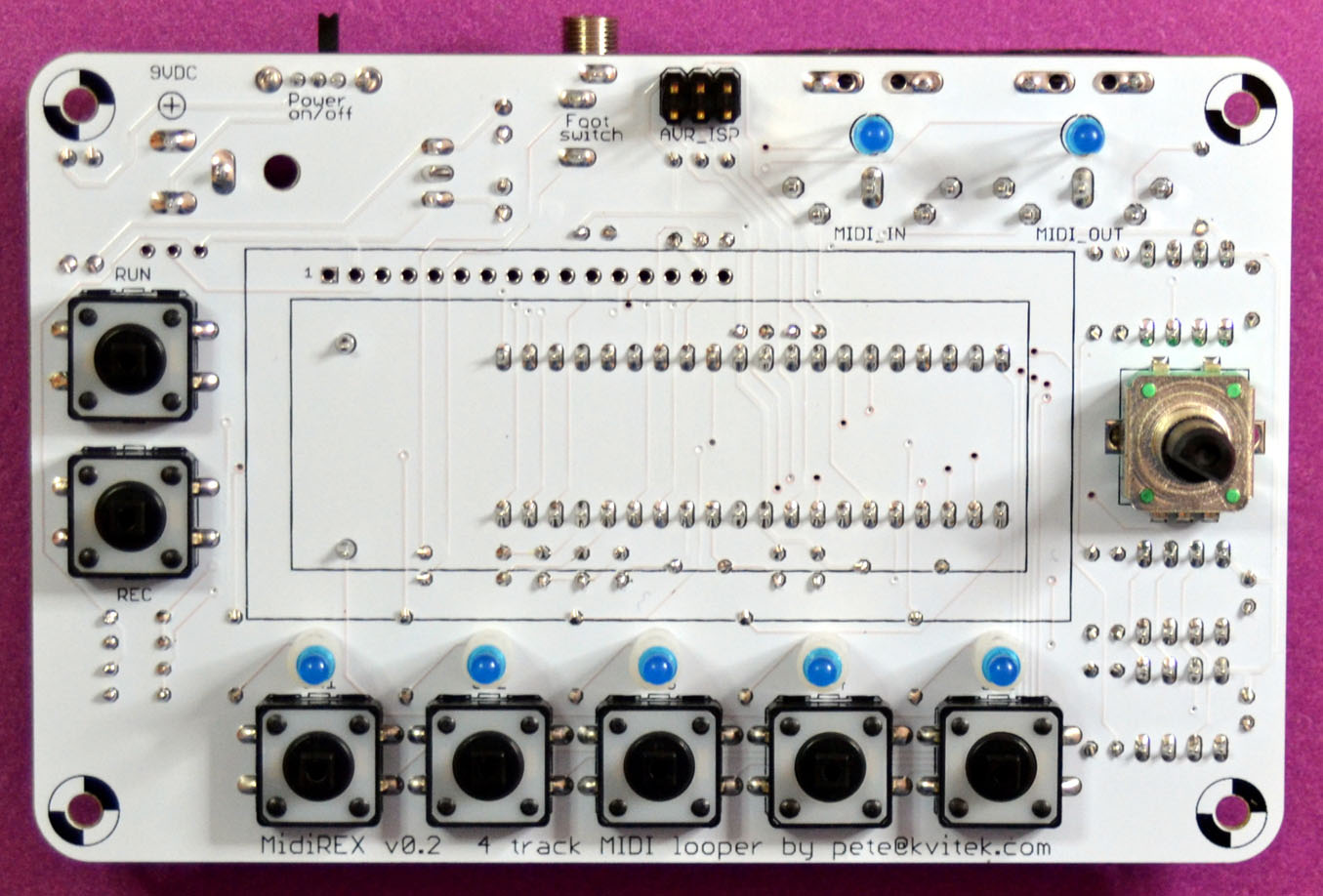
MIDI LEDs are soldered from the top since bottom is covered by MIDI connectors. Note that installing MIDI LEDs before you mount MIDI LEDs is not a good idea since you will have to file LED’s solder joints perfectly flush to the PCB, risking to damage it. Soldering LEDs from top is much easier.

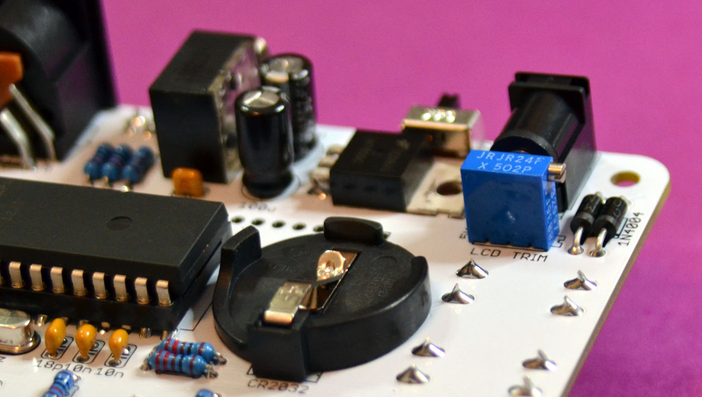
Add LCD contrast trim potentiometer. Please note that you will need to turn this trim pot up to 20 times in one or the other direction before you can see the characters on the LCD screen.
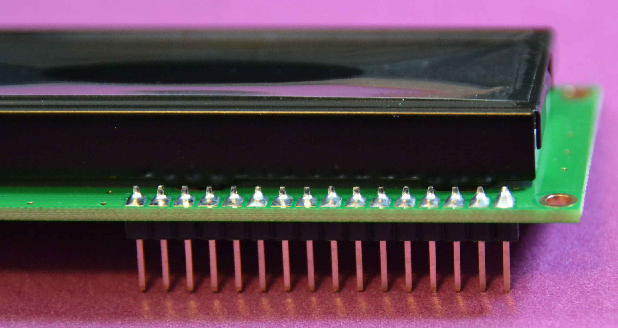
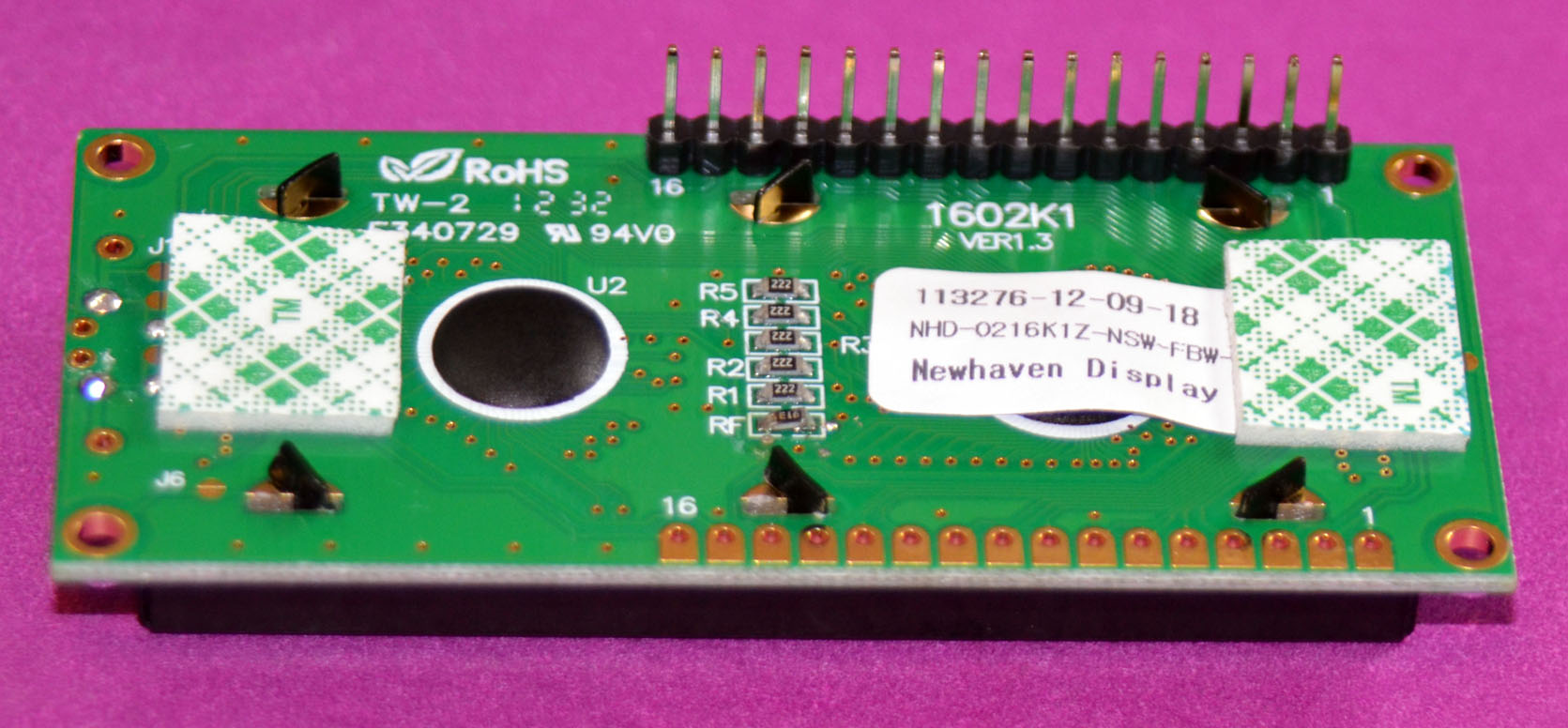
Solder 16 pin header to LCD panel:
Add double sided tape of appropriate thickness to hold the LCD:
Install LCD. It’s a good idea to cut the solder joints underneath the LCD and protect them with the piece of electrician tape to ensure they don’t come in contact with LCD panel stand offs.
Soldering in LCD header to the board is a little tricky since there is no much space in there but perfectly doable with some care.
You may want to trim the long header pins:
Install ICs and CR2032 battery:
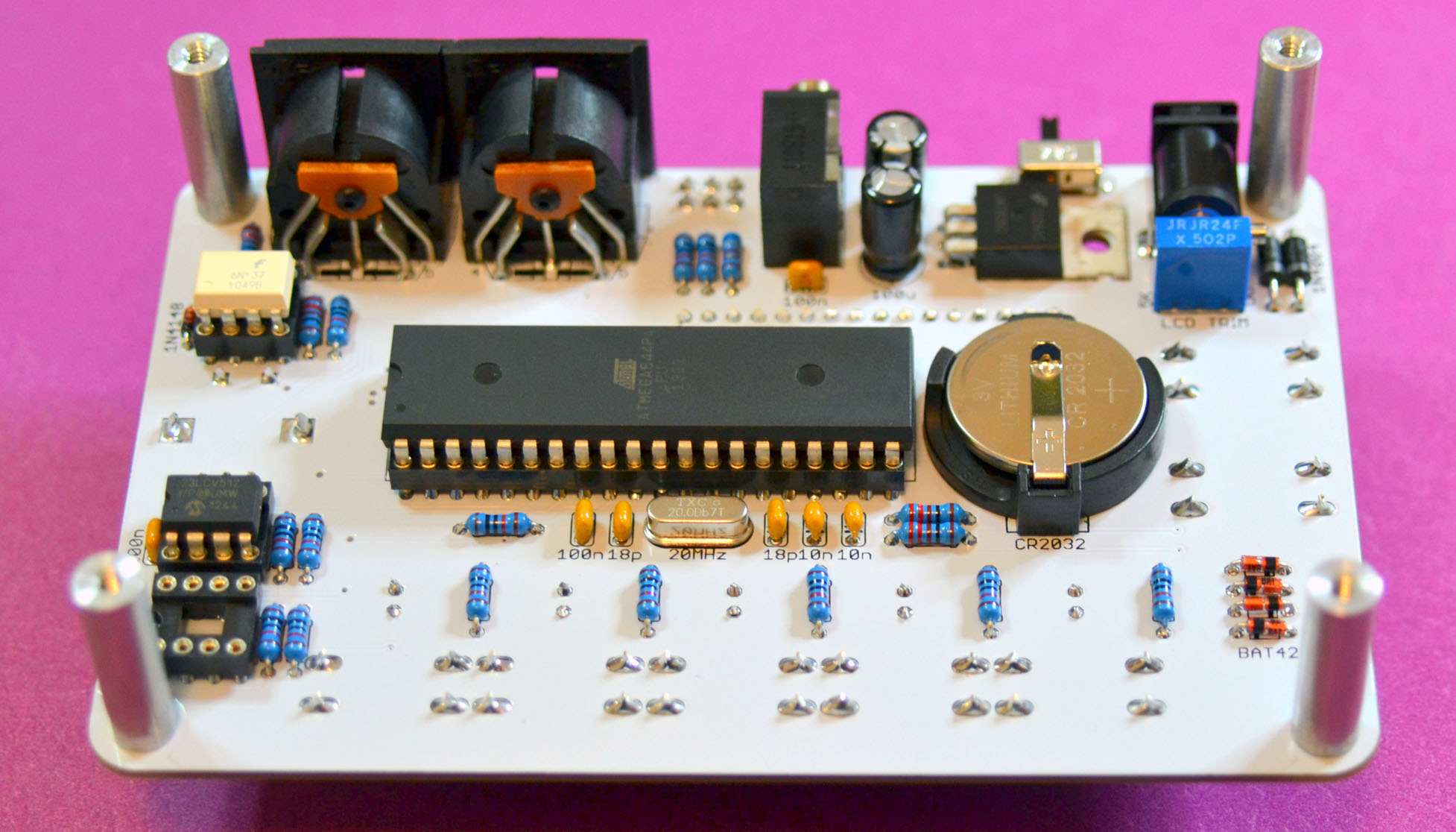
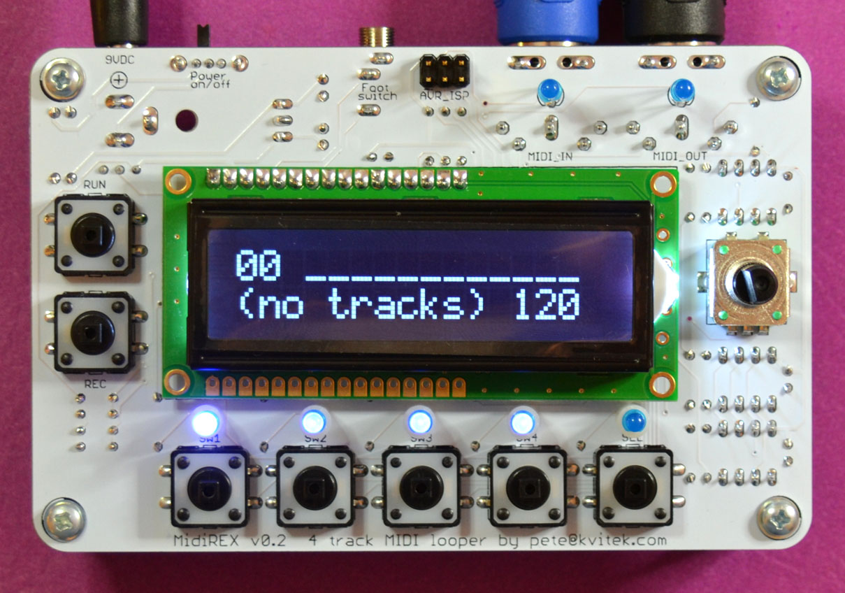
Finished MidiREX:
Important note: please DO NOT insert the second 23LCV512 SRAM chip. Current firmware supports only one 23LCV512 chip and it should be inserted in the socket closest to the encoder. Inserting the second chip won’t damage anything however MidiREX will not remember recordings when it is switched off.

I’ve just finished my build. The unit powers up and the buttons are responsive, causing LEDs to blink or hold as you’d expect.
However, nothing is displayed on the LCD. The backlight is on, but no characters are displayed. I’ve turned the trimpot from one extreme to the other without seeing anything. Any ideas on where to start trouble shooting?
Thanks in advance!
if you did not see a line of block characters at one of the extreme positions of LCD trim pot, something is wrong with the trim pot or its traces to the LCD, or the LCD itself.
Just finished my build and I’m having the same issue as @godawful. i removed the trim pot and tested it with the multimeter; it’s reading ~5k ohms as expected. there is continuity between the holes in the PCB for the trim pot and the backlight pins on the LCD. sounds like the LCD is the problem.
Is there a good way to troubleshoot the LCD itself? or should I just order another one?
I;ve installed hundreds of LCDs from various suppliers, and have seen probematic one only once — it had a few dead pixels.
So before trashing your LCD make sure that all the control and data lines to it have continuity and are not shorted.
Midirex built and tested with only the minor hiccup of an IC pin bending in causing some erratic behaviour. All fixed and this thing rocks. Well chuffed with the immediacy of it. Looking forward to my Altitude cases. Great stuff Pete!
Congrats on the successful built!
Hello,
Very good idea !
PCB and MCU are in stock to date?
Have you a suggestion for the box?
Best Regards.
Jean-Philippe
Yeah, MidiREX pcb and mcu are in stock. Proven plexy case files are available so you can order the case in any laser cutting service like Ponoko. I will also offer case kits soon.
Hi !


This is my midirex in his enclosure :
Very very good machine !!!!
Wow, impressive build!
Wow, that is beautiful!
Hi !! Is there a video of the device in operation ? Thanks !!
Where can one obtain the peripheral items like buttons and encoder know? Any recommendations ?
DigiKey or Mouser, see the BOM here: https://docs.google.com/spreadsheets/d/1SkD-uk9lj6O9TZh9gKA-0dwaPZ64ojK8r_wY0vH9a7c/edit#gid=0
Oh okay. Thx. I have the BOM imported into a DigiKey cart, I didn’t notice the peripheral stuff. Thank you for clearing that up. Merry Christmas
Hello,
The PCB I received has 10k printed, rather than 220r as pictured, for the LED resistors. Do I still abide by the rules in the guide? 10k for high intensity blue or white, 220r for everything else?
Thx!
Absolutely. You’ve got the latest v3 PCB and this pictures have v2. Most people these days build with high intencity LEDs, so having 10K makes it simpler.
I couldn´t find the midi connectors. Could you tell me which pins or the board match with a the pins of a midi connector. TY in advance
MIDI connectors are available at http://www.taydaelectronics.com
Schematics is available here: https://midisizer.files.wordpress.com/2015/03/midigal_sch.pdf
I was there https://www.taydaelectronics.com/catalogsearch/result/index/?dir=asc&order=relevance&q=midi
but still coudn´t find it.
https://www.taydaelectronics.com/5-pin-midi-connector-female-right-angle.html
I have built a midirex on a proto board.
When trying on a Clavinova Piano it seems that receiving Midi seems to work (leds are blinking) but on midi out I only see the midi clock signal and never any note. Nor the click beat.
Parameters as track names are stored etc. but it says always (no tracks)
Looking at the source v0.93 I see that there is an option for debug output.
However Atmega 644 has only one USART which is needed for the midi.
Is there a way to get Debug-output?
(I am using a 23K256 ram with level shifters. The ram works.)
ATMega 644 MCU has 2 serial ports, the second one goes to PD2/3 which are connected to FootSwitch ports.
MIDI I/O should work without RAM, MIDI events will be passwed through from IN to OUT.
Great, Thank you for this excellent hint! Debug output works now for me after specifying:
DebugOutput< SoftwareSerialOutput< Gpio, 57600> > dbg;
By this I found out that the Frequency of my Atmega was 16 MHz and not 20 MHz what would give wrong Baudrates.