Being assembled correctly, MidiALF works right away and does not need any tuning besides LCD contrast setup. If you have any problems with the build, please check MidiALF Assembly and Troubleshooting forum to see if anyone had similar issue and if not, post your symptoms there.
Troubleshooting electronic circuits is a form of art, so there is not way we can provide steps to resolve all possible problems, however here are a few tips that will hopefully help you pinpoint the problem.
Power
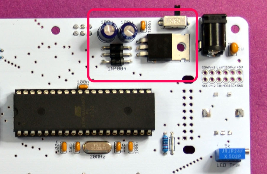
If your MidiALF board is missing +5V, make sure you’re using a correct power supply (9V DC with center pin positive, 300mAh minimum), power switch is in On position, then check solder joints around LM7805 voltage regulator and the following:
- D1,D2,D3 polarity
- C3,С4 polarity
MIDI input
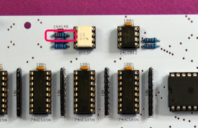
If MIDI input does not work, check solder joints around MIDI IN connector, 6N137 optocoupler and the following:
- 6N137 and R8, R9 and D4
- 6N137 pin 6 connection to MCU pin 14

MIDI output
If MIDI output does not work, check solder check solder joints around MIDI OUT connector and the following:
- R10
- MIDI OUT pin 5 connection to MCU pin 15
Step LEDs
Step LED’s are driven by the left 74HC595 and 8 current limiting resistors, so check solder joints and shorts in this area:

You may also want to check solder joints and shorts around these MCU pins: 35, 36 and 1.
Switch LEDs
Switch LED’s are driven by 74HC595 and 8 current limiting resistors on the right of the PCB, so check solder joints and shorts in this area:

Relevant MCU pins are 35, 36 and 1.
Side Switches
Side switches are polled by the rightmost 74HC165 and the resistor network between this IC and MCU:
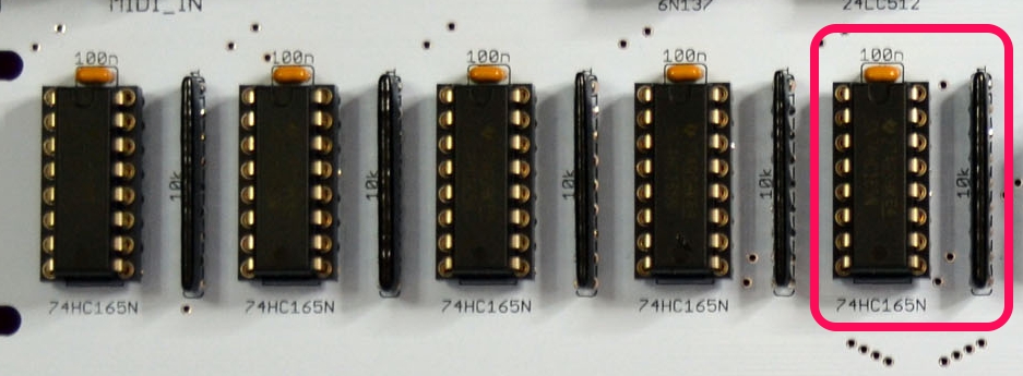
Relevant MCU pins are 37, 38 and 1.
Step Switches
Step switches are polled by the second 74HC165 from right and the resistor network on its right:
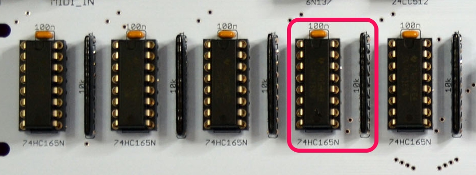
Relevant MCU pins are 39, 40 and 1.
Step Encoders
Step Encoder clicks are handled by the leftmost 74HC165 and the resistor network next to it:

Step Encoder rotation is handled by the second and third 74HC165 and the respective resistor networks:

Relevant MCU pins are 1, 2, 3, 4 and 5.
Left and Right Encoders
Left and right encoders are hooked up directly to MCU ports 24, 25, 26 and 27, 28, 29 respectively.
Good luck!
