This BOM is for main board w/o CV extension. If you’re going to build CV extension, please replace LM7805 with its switching mode equivalent and make sure you order C3 with 25V rating. See more details here.
LCD options
Selecting LCD is a great way to personalize your MidiALF. Pretty much any HD44780 compatible 40×2 LCD with 16 pin connector on the left side will do, however keep an eye on dimensions and mounting hole locations. Also, make sure to check LCD documentation for recommended current limiting resistor value: most 40×2 LCDs have it on-board, so R7 is shunted. However, some other LCDs and most OLED LCDs will require a resistor. If go trial and error route you may want to start 68 ohm resistor, then go down if back light LED does not turn on.
Here are some LCDs that are known to work well:
- ebay user egochina8848 sells inexpensive and pretty high quality white-on-blue LCDs, you see it on the purple board prototype unit and first production “white pcb” MidiALF.
- Newhaven has some nice 40×2 LCDs here, however they seem to be pretty current hungry comparing to the ones from ebay above. Mouser part number is 763-NHD-0240AZ-FLYBW.
- Digikey stocks excellent Kyocera (ex. Optex) display part 73-1260-ND. It looks great but is %30 more expensive than your average 40×2 LCD. ATTN: this LCD needs 68ohm current limiting resistor R7 to work properly.
- BuyDisplay has some nice black on white LCDs here.
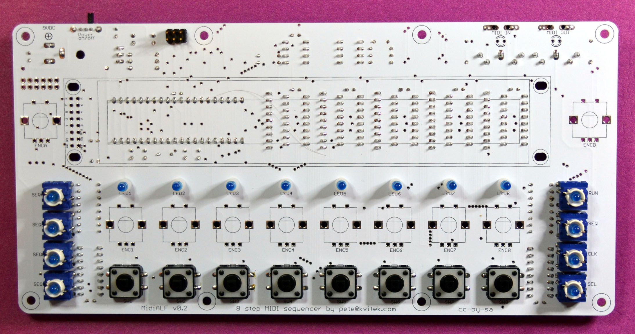
Component side assembly
The bare pcb de-greased with isopropyl alcohol:

Add resistors:
- 20 x 221 Ohm
- 2 x 10K
- 2 x 2.2K
- 1 x 0 Ohm (wire jumper)
Note: if you’re going to use high intensity blue or white LEDs replace 221 Ohm current limiting resistors (green boxes) with 10K resistors:
- 2 x 221 Ohm
- 20 x 10K
Make sure resistors are oriented consistently. Random step LED resistor orientation not only looks ugly, but also (according to ALF), results in a less stable clock.

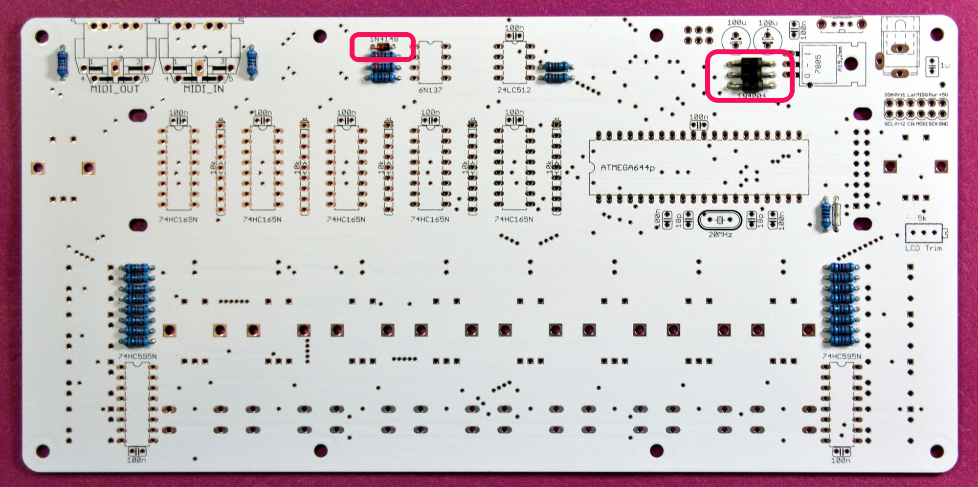
Add diodes:
- 1 x 1N4148
- 3 x 1N4004
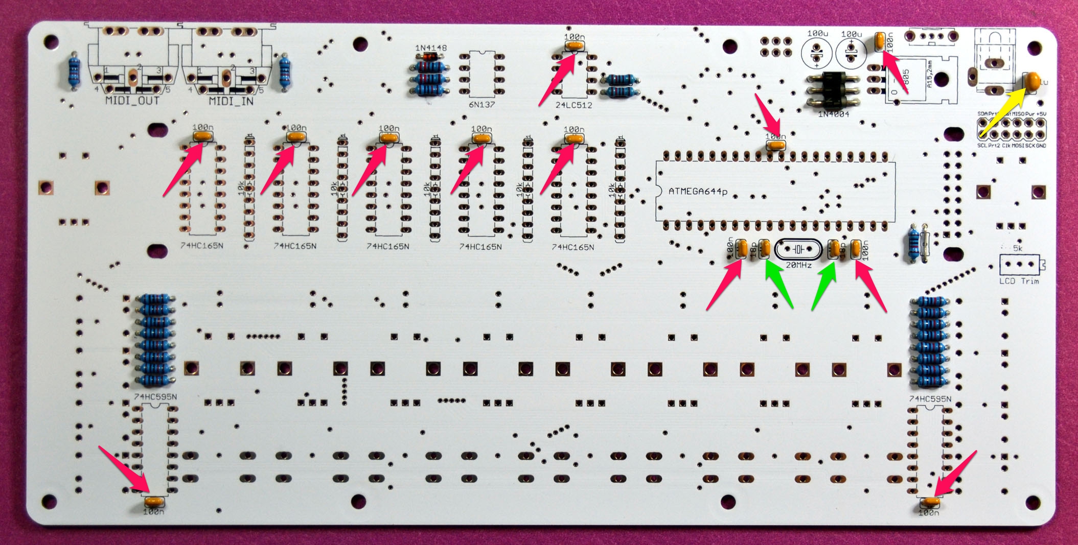
Add ceramic capacitors:
- 12 x 0.1uF (red arrows)
- 2 x 18pF (greed arrows)
- 1 x 1uF (yellow arrow)
Add LM7805 and a 20MHz quartz.
NOTE: if you’re planning to build MidiALF/CV extension, do not install LM7805 voltage regulator and read here.

Add resistor networks. Note that these are polarized: marked pin should be at the top.


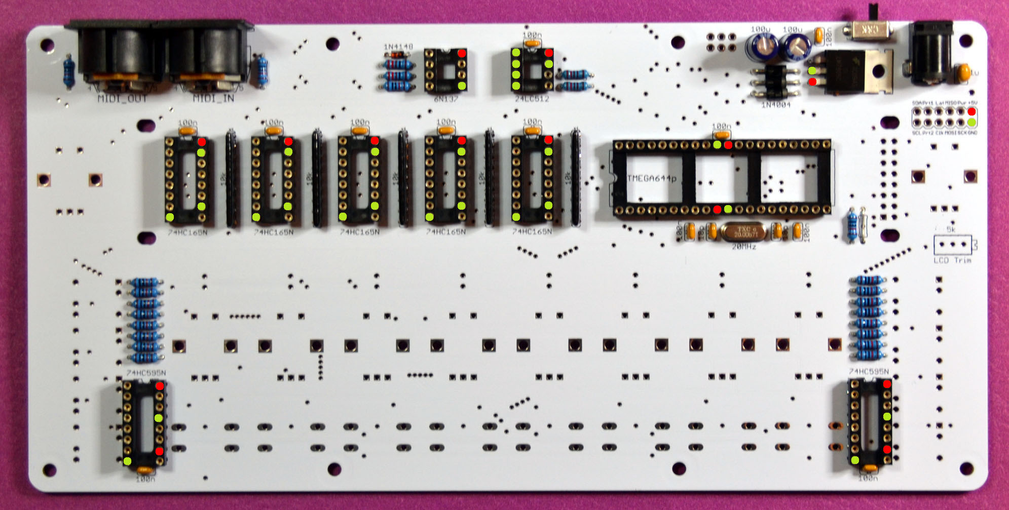
Add IC sockets. Make sure that the notch is at the top for 8 and 16 pin sockets and on the left for 40 pin socket!
- 2 x 8 pin
- 7 x 16 pin
- 1 x 40 pin

Add 2 x 100uF 16V electrolytic capacitors. Note that these are polarized!
NOTE: if you’re planning to build MidiALF/CV extension, do not install these capacitors and read here.

Add DC power switch and connector:

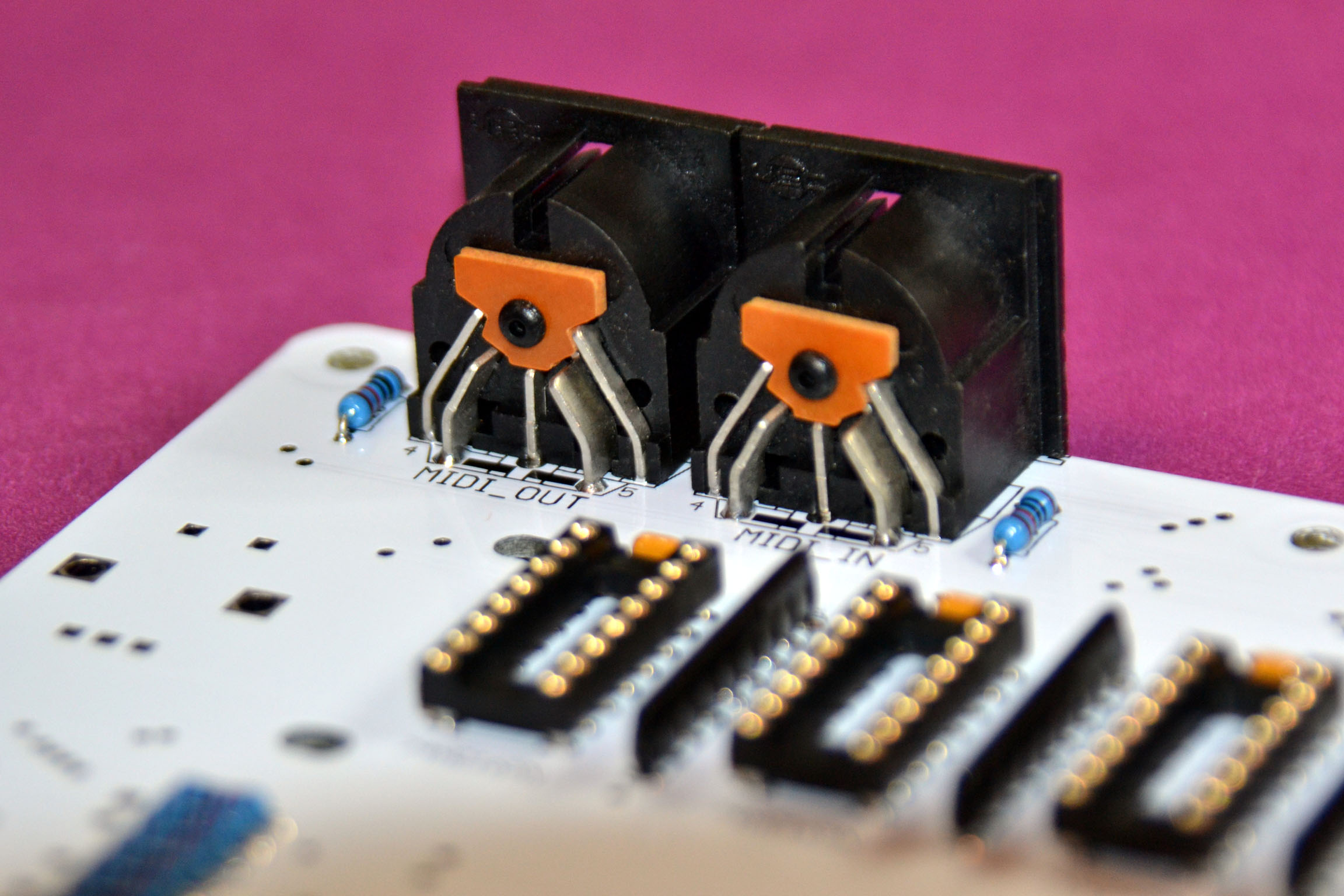
Add 2 x MIDI connectors:
Solder in LCD contrast trim pot on the component side. Please note that you will need to turn this trim pot up to 20 times in one or the other direction before you can see the characters on the LCD screen.

Add miscellaneous parts:
- 3×2 AVR ISP header (if you’re using a programmer)
- 2×5 header (if you plan to use CV extension board)
You’re done with the component side! Time to wash the board, dry it out and thoroughly inspect all the solder joints with the magnifying glass.
Power supply tests
Check connectivity between all ground pins (green pads), then between power pins (red pads). Verify discontinuity between ground and power rail (red and green pads). Hook up 9V DC power supply (center pin positive, 300mAh and above) and check for +5V being present at all red pads.
Face-plate side assembly
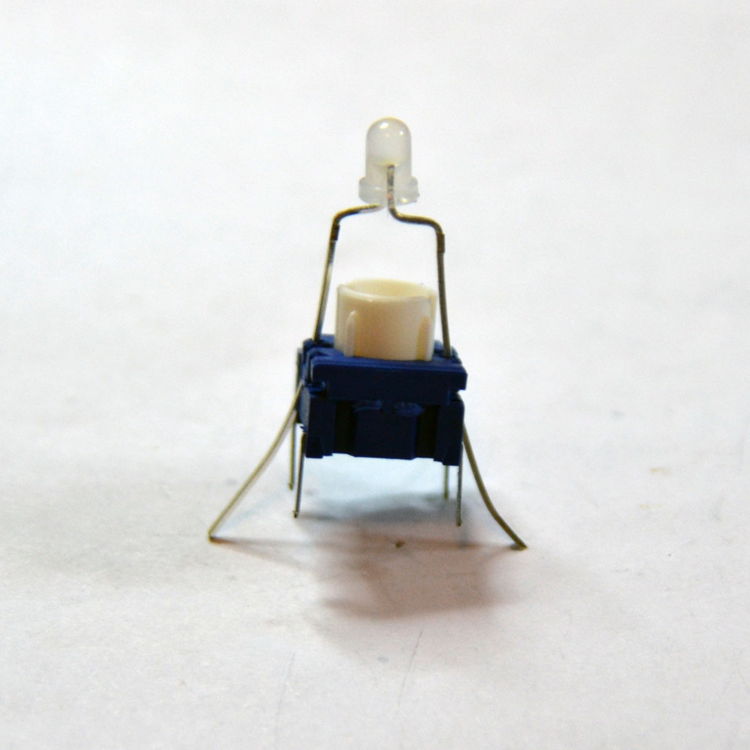
Solder in 8 step switches and 4+4 side switches with LEDs. Note that LED’s are polarized: the long leg (anode) goes to the right.


DigiKey stocks MEC 3FTH9 LED switches with and without LEDs installed. You may want to buy the ones without LEDs since they are half the price of the ones with the LED installed and you can choose better looking diffused LEDs. Installing LEDs into switches is pretty easy: just bend the legs and slide them into the opposite holes on the switch.
Note that pictures show older 3FTL6 LED switches which are now discontinued and replaced by newer 3FTH9 LED switches, which are all black.


Solder in step LEDs — the long leg (anode) goes to the bottom, closer to the step switches. Don’t forget to install spacers! .300″ spacer work really well with Frank’s plexy cases.

Unless you’re planning to build MidiALF/CV board, solder in 2 x MIDI LEDs (short leg facing the other diode). These are soldered from the top since bottom is covered by MIDI connectors. Note that installing MIDI LEDs before you mount MIDI LEDs is not a good idea since you will have to file LED’s solder joints perfectly flush to the PCB, risking to damage it. Soldering LEDs from top is much easier.

Solder in 8+2 encoders:

Almost done! At this point the only missing part is 40×2 LCD. It covers MCU and input shift register ICs soldering area so it is important to verify that everything works before LCD is installed.
Testing encoders, switches and LEDs
Install all integrated circuits, including pre-programmed micro-controller chip. Watch the orientation: small ICs should have the notch pointing to the top, and microcontroller chip notch should point to the left. Verify orientation! Reversing the ICs will most probably damage it when power the unit up.
If you got a bare MCU chip, it’s time to flash it.
Connect your best synth to MIDI OUT. You can also hook it up to your computer’s MIDI In and use MIDI tracing utility like MIDI-OX.
Switch MidiALF power on while holding down the Encoder B (the one at the right of the LCD) to start MidiALF with freshly initialized sequence.
Test the left side buttons by pressing them one by one, the pressed button LED should light up.
Click the Encoder A at the left of the screen and check if 3 of the 4 left side button LEDs are pulsing, and one is fully lit, click Encoder A again to cancel mode.
Press RUN button (the top one on the right side). The RUN button LED should light up, the step LEDs should start running, and C4 notes with velocity 100 should be sent at 120BPM to MIDI Out.
Verify that left encoder transposes all notes in sequence up and down. Repeat while holding down the SEL key (bottom right), all notes should be transposed by an octave.
Verify that step encoders transpose step note up and down.
Verify that clicking step encoder plays the note and glows the step LED.
Verify that step switches mute the step.
Change a few notes in the running sequence so that you can hear the difference, then press SEQ button (second from top), rotate EncB to the right, then click it. The running sequence should revert back to all C4s.
Verify that the CLK button slows down sequence.
Connect your MIDI keyboard to MIDI in and verify that pressing the key transposes the sequence while it is running.
If everything checks out you are good to go. If not, refer to Troubleshooting section and fix problems before soldering in LCD.
LCD installation
Cut IC and resistor network pins in the area below the LCD. There is no need to cut them flush, however you don’t want solder joints to be higher than 1mm. Stick two pieces of electrician tape to cover solder joints under the LCD area to ensure that they will not come in contact with LCD board:

Solder the 8×2 pin header to the LCD, mount LCD using the plastic bolts and nuts (use one as a spacer between LCD and the PCB), then solder the pin header in.
Switch on the MidiALF and adjust LCD contrast by using LCD trim potentiometer. It may take up to 20 turns in one or the other direction before you will see any characters.

Finished MidiALF.
Party time! Get yourself a beverage of your choice, press and release SEL button (bottom right) to show Command page, click step Enc1 to activate Randomizer mode, select a music scale to match your current mood by rotating EncB at the right of the screen. You may want to quickly check how the selected scale sounds by “strumming” notes with the step encoders, then press RUN and click EncB to randomize the sequence within scale.
When you find the sequence that sounds interesting, correct imperfect steps by randomizing just one step with the step button press or transpose it (also within scale) by rotating the step encoder.
Make a nice picture of your freshly build MidiALF (even if it’s naked) and post it here.
Have fun!

TL1100 are out of stock both digikey and mouser.
Will 612-TL1100-6JBLK work?
yup
I read quickly the instructions for building alf and cv boards. Everything seems clear except the Midi LEDs. Why aren’t they soldered if you are building the cv version?
The I/O port used to drive MIDI LEDs are used to communicate with /CV extension board. There are not enough I/O ports, so they had to be re-purposed.
Just finished the Midialf, and it does what is´s supposed to! Great piece of fun! But it´s running the 93d version, and I`d like to update to version 94 thru sysex. I have the cv-extension board as well, is it enough then to only download the 94 cv- version? Regards
Yeah, grab the latest firmware from here: https://midisizer.files.wordpress.com/2013/01/midialf_094.zip and send “midialf_094_cv.syx” via midi.
Thank you – on behalf of my husband, who forgot to sign me out… 🙂
IC-sockets seems to be out of stock at digi-key. it is possible to update the google-doc? I found a nice display. German store: http://www.reichelt.de/Hintergrund-blau/LCD-402A-BL/3/index.html?ACTION=3&GROUPID=3006&ARTICLE=53953&OFFSET=16& . You think, this will this work?
Those are standard sockets — you can choose any part with matching amount of pins. Yes, this display appears to be compatible, however way too expensive — same display at buydisplay.com goes for < $10
Hi Peter —
Any tips on testing the power supply when doing the CV build (using C3 cap and DC/DC converter on main board)? I have the correct wall wart…just wondering if I’m going to fry anything at this stage (sans hooking up the CV board).
If you have socketed ICs, I’d remove them all from both boards, power up the ALF and check all voltages. Before doing this i recommend double and triple checking installation of the DC to DC converter on the main board. if in doubt, email me a hi res photo of both sides.
Hi Peter. I’m planning on having white LEDs for left and right side selectors, and orange for step LEDs. They require different resistor-values, and I can’t figure out which of the 16 resistors in the lower half of the component side of the board, go to which LEDs.
8 x resistors in the group on the left of the are for horizontal step LEDs, similar group on the right is for both groups of vertical LEDs.
Awesome, thank you!
Hi, is there a brd. files for DIY ?
Thank you
best
HI, is there a way to invert encoder directions?
Yeah, but you will have to build your own version of the firmware. The change is in “avrlib\devices\rotary_encoder.h”, swap lines 54 and 57
I don’t understand why, if you use higher power LEDs, you should use higher rated resistors. Your BOM gives 20mA@2.2V LEDs for 220 Ohm resistors. I would like to use 20mA@3.5V white LEDs. Are 10kOhms resistors really OK for these LEDs?
10K current limiting resistors are fine for most blue and white diffused LEDs. However, you may probably find some high intensity LEDs that would need more than 10K.
Okay thanks. I thought the relevant parameters of resistor selection for LEDs were forward current and rated voltage of the specific LED used. I’m just surprised that the differences in Ohms is 50-fold when the specs differ only in about 1 volt between the green and white LED. For sure I don’t get this right!
Hi, I’d like to build one of these, but I’m having trouble finding some parts in the BOM.
Firstly, LED’s. The ones you listed aren’t available online through mouser, so I thought I’d looks for some blue LED’s.
Would 593-LTH3MM12VFR4600 do the trick if I used 10k resistors?
Secondly, 512-LM7805CT is discontinued, would 863-MC7805CTG be fine?
Once I price it all I’ll be looking to order a board, too.
Any 3mm LED will do, however it is recommended to use 10K current limiting resistors for modern high intensity LEDs (blue, white, etc).
Any LM7805CT will do, from any manufacturer, it’s a jelly bean part.
Thank you. Now I just need a decent screen.
Am I correct that if the LED screen has a limiting resistor, I don’t need the R7?
If I could get a PayPal invoice to the email address supplied, I’ll grab 1 main board and 1 pre-programmed ATMega644p. Thank you. 🙂
Actually, I have a spare ATMega644p, so just the board to Australia please. 🙂
Just finished building this, almost. Waiting on some standoffs to get the LCD on.
So far, it’s working great, except it’s sending C3 notes instead of C4. I’ve got it plugged into a DAW but have also used “Midi Monitor” to cross check.
Any ideas what could be wrong?
Hmm, the one think I haven’t troubleshooted is the cable itself.
I’ll see if I can find a different cable.
Unfortunately, it wasn’t the cable. I tested it with a MIDI keyboard featuring a 5DIN out as well as a USB MIDI out, switching between the 2. Both notes received by my DAW via USB and 5DIN are the same.