MidiALF CV extension progress

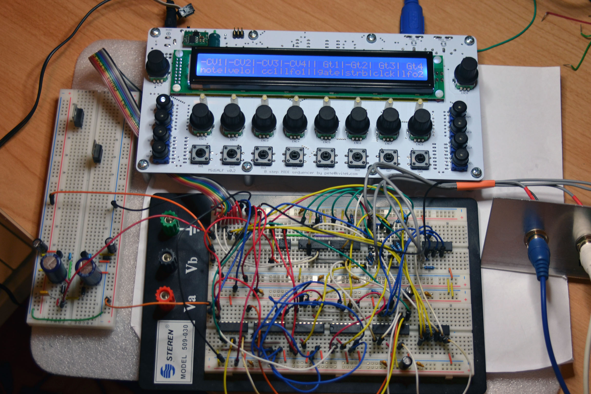
MidiALF CV extension breadboard prototype is done!

There are 4 x CV outputs with configurable range (-5+5V or 0-10V) .  Each CV output could be set to Note (1V/Oct), Velocity, CC1/2 or LFO1/2. There are also 4 Gate outputs with configurable polarity. Each Gate output could be set to Gate, Strobe, Clock, Sequence start strobe and LFO1/2. Gate outputs 3 and 4 are available only at expansion connector, there will be no on-board jacks for them due to lack of board space.

MidiALFCV_breadboard

CV extension board will have the same size as the main board and will be attached to the stand offs at its bottom. There are 6 x 1/4″ jack connectors at the top (4 x CV, 2 x Gate). I also plan to add 3.5mm connectors so it could be built for Euro rack standard. PCB routing is going to be tricky due to the mixed signal nature of the board.

Important note for those who plan to build CV extension board

CV extension board needs +/-12V to do its job, so the main board has to be powered by 12V AC adapter. Because of this, the following changes need to be made:

  • 7805 voltage regulator has to be mounted on a decent heat sink, or replaced with switching mode equivalent OKI-78SR-5/1.5-W36H-C (Digikey part# 811-2692-ND, Mouser 580-OKI78SR51.5W36HC)
  • C3 should be changed to 220uF/25V. With this specification the capacitor is too high to fit between main board and 1/4″ jack connector on the CV board, so it has to be mounted on the top side of the pcb, see the picture below.
  • MIDI IN/OUT LEDs and their current limiting resistors on the sides of MIDI connectors should not be mounted since  MCU ports that drive them are used to interface with CV board, so their flashes will be unrelated to MIDI activity.

I recommend to use OKI-78SR-5/1.5-W36H-C because even with a heat sink the 7805 can get pretty hot, especially if your LCD is one of those current hungry ones. With switching mode regulator the heat is not an issue at all and it’s easy to mount, see here:

Image