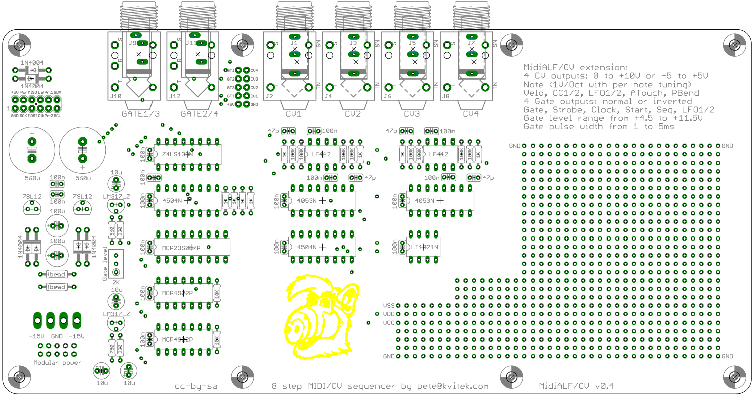
MidiALF/CV extension board is mounted at the bottom of the MidiALF main board using 8 x 7/8 stand offs. You can choose to build it with 1/4″ or 3.5mm jacks. It could be powered by MidiALF main board (which in this case needs to be powered by 16VAC adapter) or your modular system (+-12 or +-15V via optional Eurorack 5×2 or MOTM MTA-156 connector).
Features
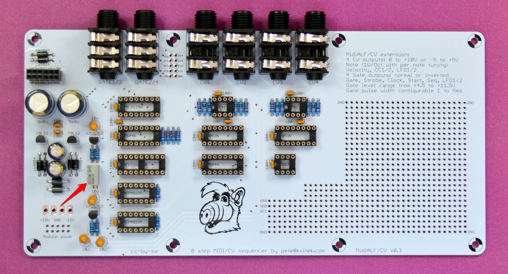
4 CV outputs: 1/4″ or 3.5mm jacks, range 0 to +10V or -5 to 5V .
Each CV output can be set to:
- Note (1V/Oct with per note tuning)
- Velocity
- CC1/2
- LFO1/2
- After touch
- Pitch bend
4 Gate outputs: 2 x 1/4″ stereo jacks (Gate1/3 and 2/4) or 4 x 3.5mm jacks, normal or inverted.
Gate level is set by on-board trim pot ( +4.5 to +11.5V).
Strobe pulse width is configurable from 1 to 5 ms.
Each Gate output can be set to:
- Gate (on while key is down)
- Strobe (pulse on key down)
- Clock (pulse 24 PPQN)
- Start (on while sequencer is running)
- Seq (pulse on sequence start)
- LFO1/2 (pulse on period start)
Large hacking area with ground and positive/negative power rails.
DIY Resources
Schematics: alf_cv#1 alf_cv#2 (v0.3)
Schematics: alf_cv#1 alf_cv#2 (v0.4)
Bill of Materials (vo.3)
Bill of Materials (v0.4)
Eagle files: alf_cv_v04
CV/Gate configuration page
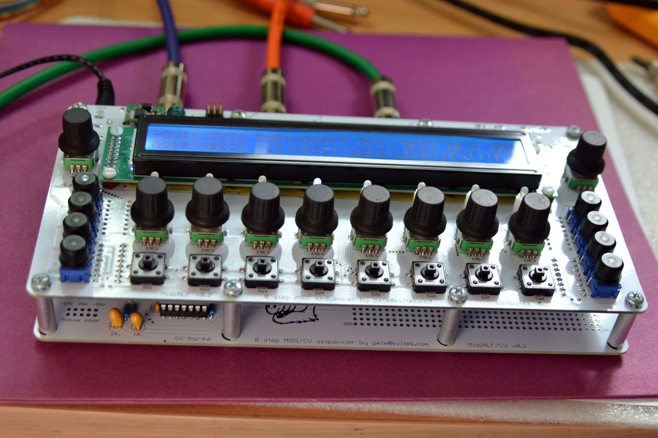
-CV1| CV2| CV3| CV4|| Gt1|-Gt2| Gt3| Gt4
note|velo| cc1| cc2||gate|strb|lfo1|lfo2
This page is shown when rotating EncA in page selection mode.
Step encoders select CV/Gate mode: note/velo, gate, strob, etc.
Step encoder click toggles CV range (0 to +10V or -5V to +5V) or inverts Gate output.
Note CV tuning page
 C4 | C#4| D4 | D#4|| E4 | F4 | F#4| G4
 -23| -21| -19| -17|| -15| -13| -11| -8
This page is shown when Tune command is selected on the Command page.
EncA shifts all notes tuning up or down 1 step (or 10 steps if SEL is held down).
EncA click resets all notes tuning to zero (with confirmation).
EncB selects visible note range, hold down SEL to shift by an octave.
EncB click saves current tuning and cancels note sound.
Step Encoders change note tuning by 1 step (or 10 steps if SEL is held down).
Step Encoders click sends the clicked note to both MIDI and CV outputs.
Step switch resets note tuning to zero or, if it’s already at zero, interpolates the note tuning.
Tuning procedure
Per note tuning covers entire CV range, so you can use it to change note CV output to whatever requirement your VCO has.
Note tuning interpolation speeds up the process significantly by estimating the note tuning value using the non zero tuning values to the left and to the right. Here’s the typical procedure:
- connect note CV output to your 1/V per octave VCO input
- connect MIDI OUT to a reference synthesizer MIDI IN
- click encoder under C4 and tune your VCO frequency controls so that VCO pitch matches reference synthesizer pitch
- rotate EncB to make C3 visible
- rotate step encoder under C3 tuning output CV so that VCO pitch matches reference synthesizer pitch
- press step switches on notes between C3 and C4 to interpolate their tuning, manually tweaking each note tuning after interpolation if necessary
- Repeat steps (5) and (6) for all octaves you want to cover.
Note that if note CV output has been tuned before, but sounds out of tune the next day, you may want to try rotating EncA shifting all notes tuning up or down first to bring C4 in tune.
Ordering
To order MidiALF/CV extension board, please send an email to pete at kvitek c o m specifying how many PCBs you need and a country where to ship them, and I’ll send you PayPal invoice.
MidiALF/CV board $30 (please note that you’ll need MidiALF main board to use this extension board).
Shipping:
- Continental USA — $5
- Canada – $10
- Europe, Asia and Australia – $15
Building MidiALF/CV
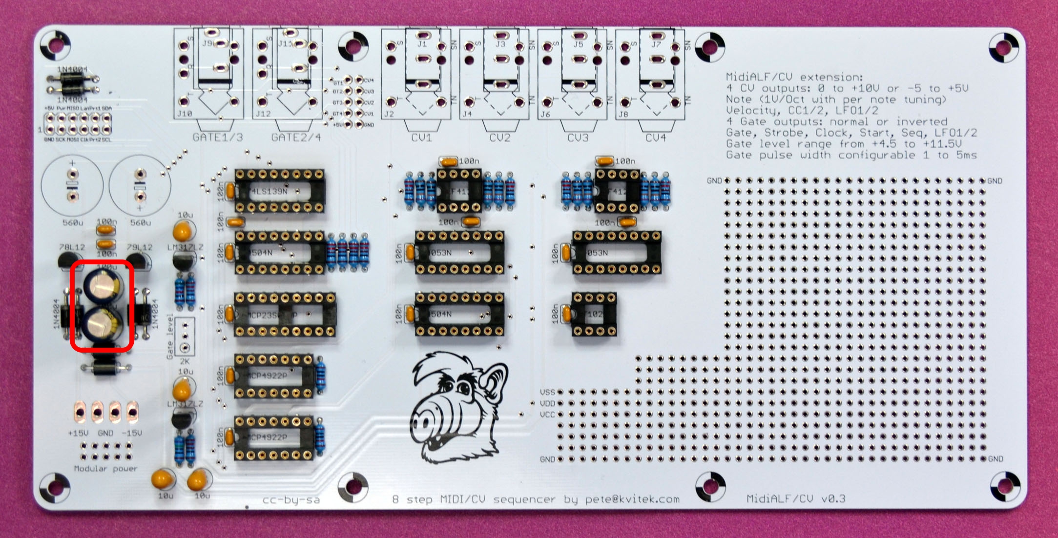
If you have soldered LM7805 on your main MidiALF board, you’ll need to replace it with switching DC to DC converter: RECOM R-785.0-0.5 part . Unless you have a re-work station or a good desoldering tool, I recommend cutting the legs of 7805 and then desoldering them one by one. It is not worth risking MidiALF PCB pads attempting to save 50 cent component. When all three legs are removed you can clean the pads with a solder wick and solder in 3 pin header to make it easier to install DC to DC converter. You will also need to replace C3 with 220uF electrolytic capacitor with 25V rating, mounting it sidewise because there is not enough room to mount vertically: the connectors on the CV board leave very little space in the sandwich.

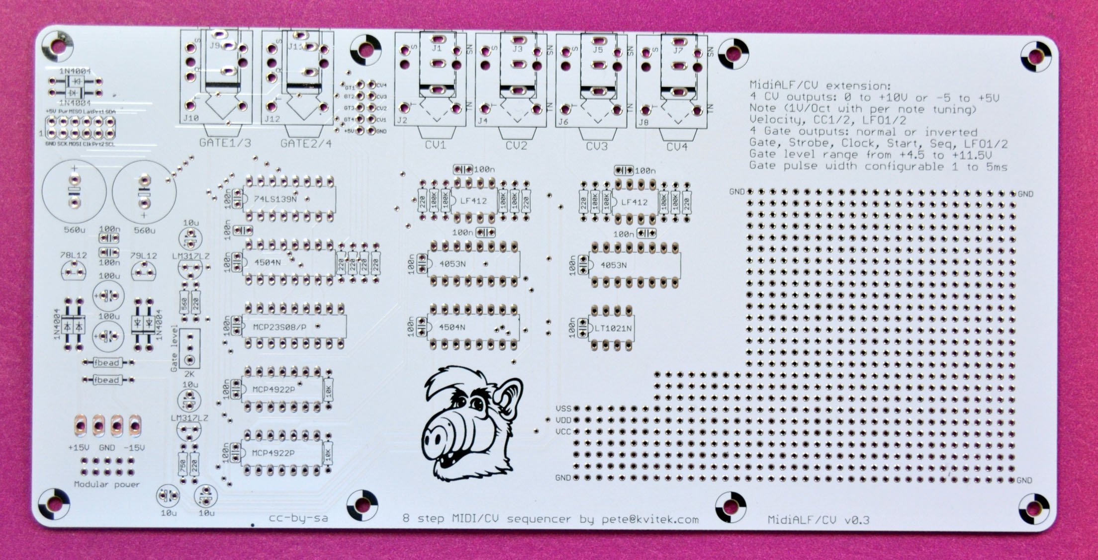
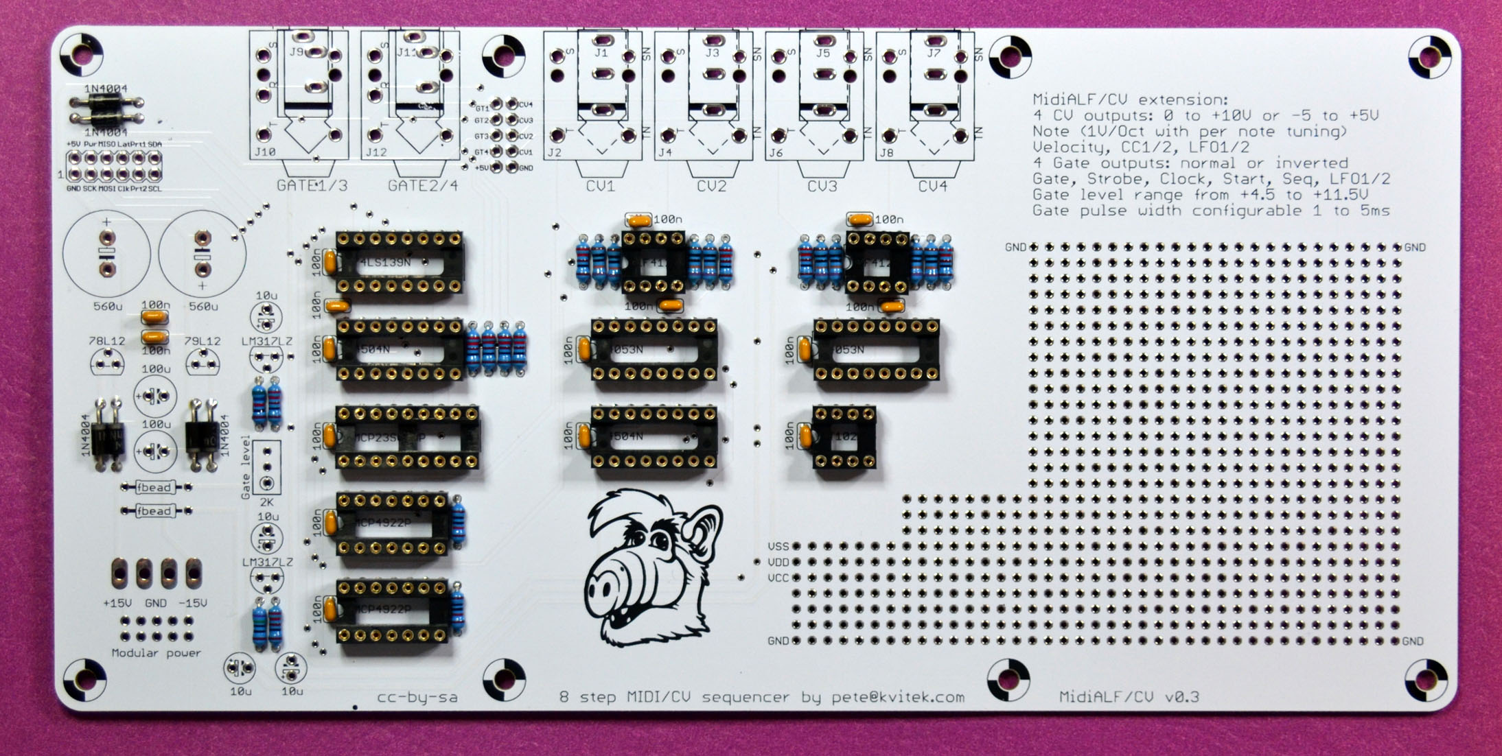
The bare pcb de-greased with isopropyl alcohol:
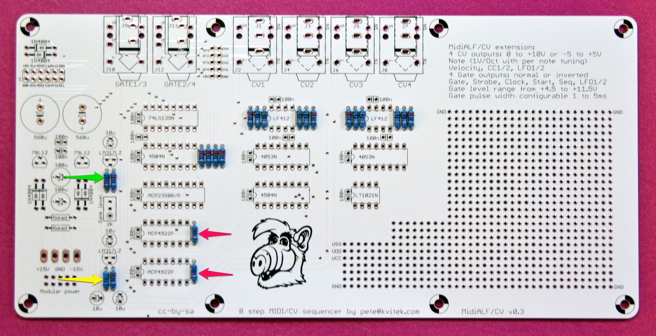
Add 10 x 220 ohm resistors (v0.3). For v0.4 add 2 x 220 ohm resistors on the left and 8 x 1K resistors next to 4504N and LF412:
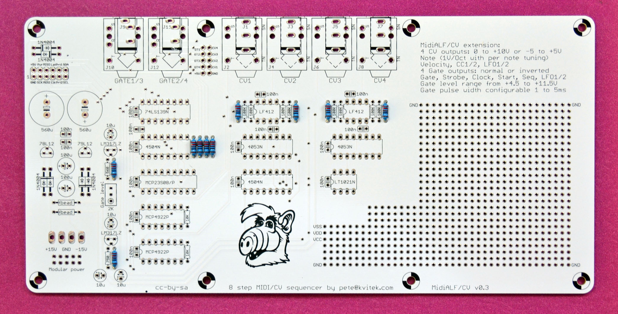
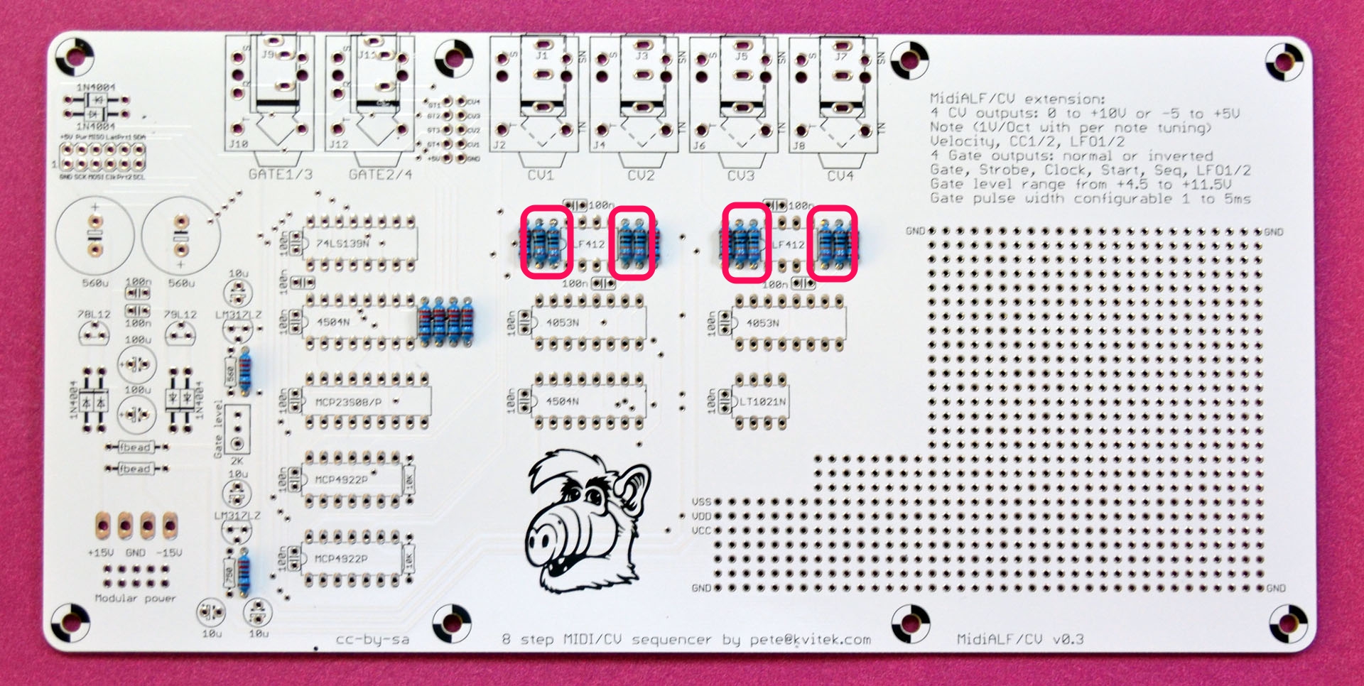
Add 8 x 100K 0.1% resistors:
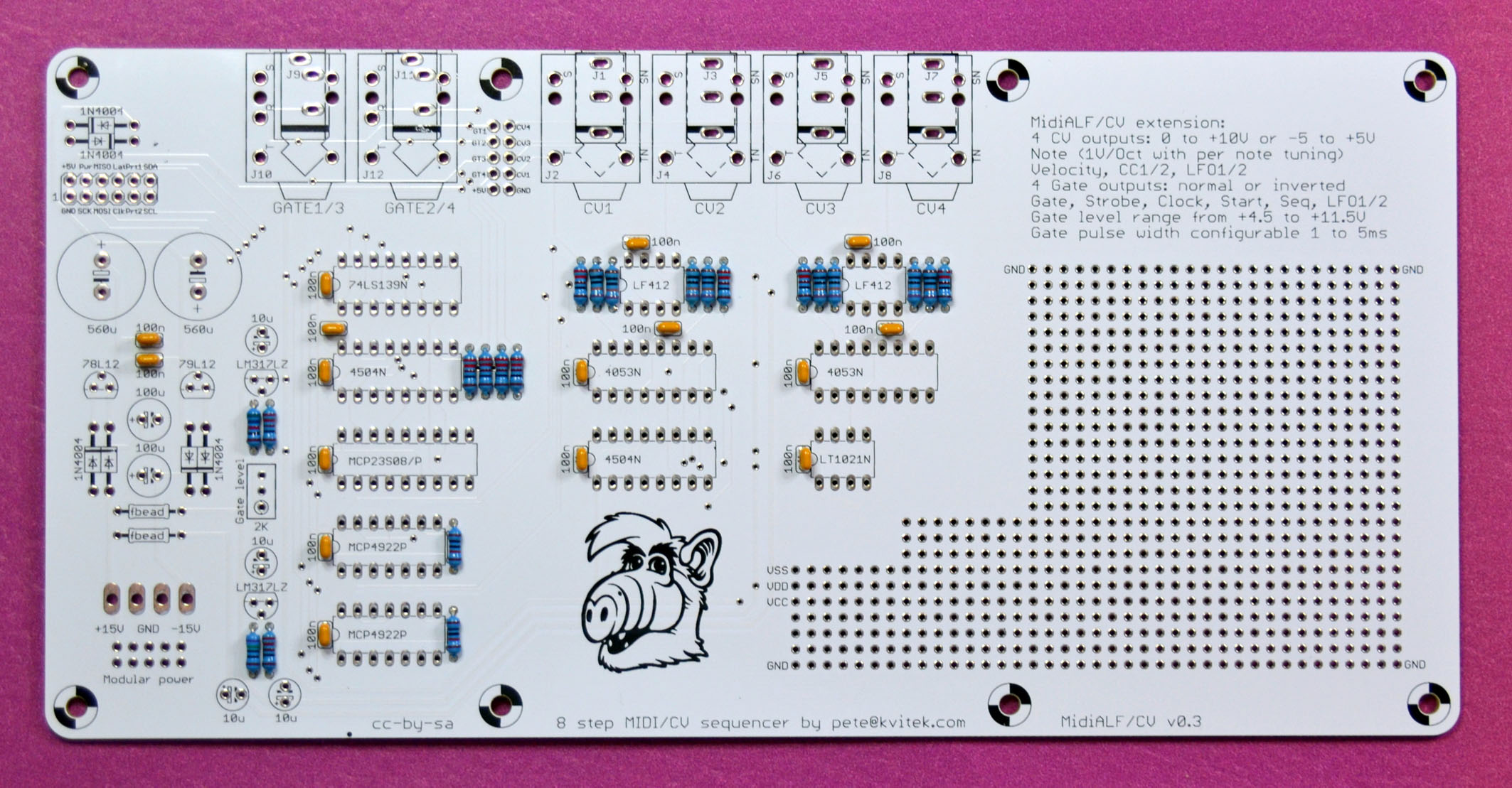
Add miscellaneous resistors:
- 2 x 10K
- 1 x 750
- 1 x 560
Add 16 x 100n capacitors. For v0.4 add 4 x 47p capacitors.
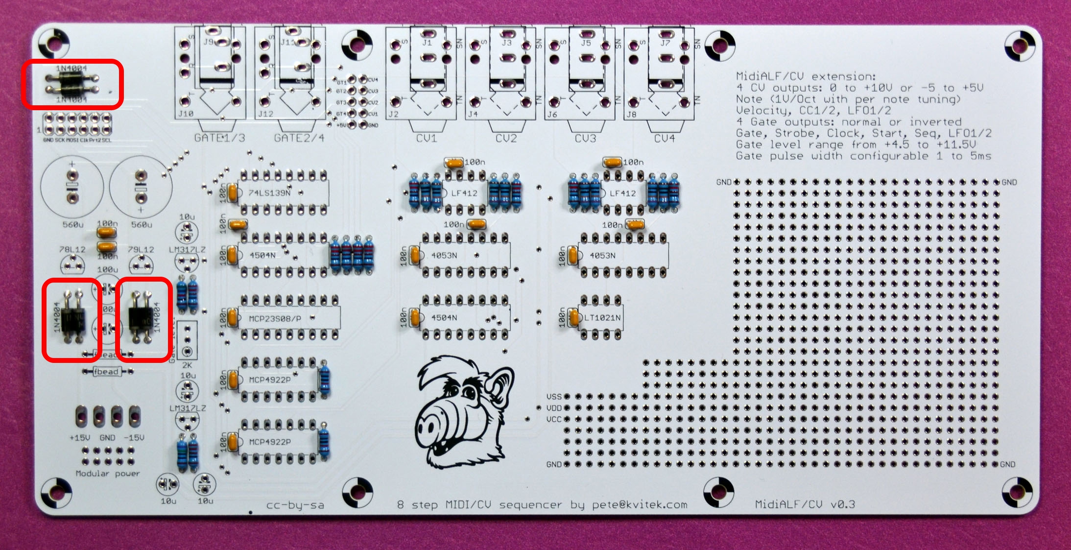
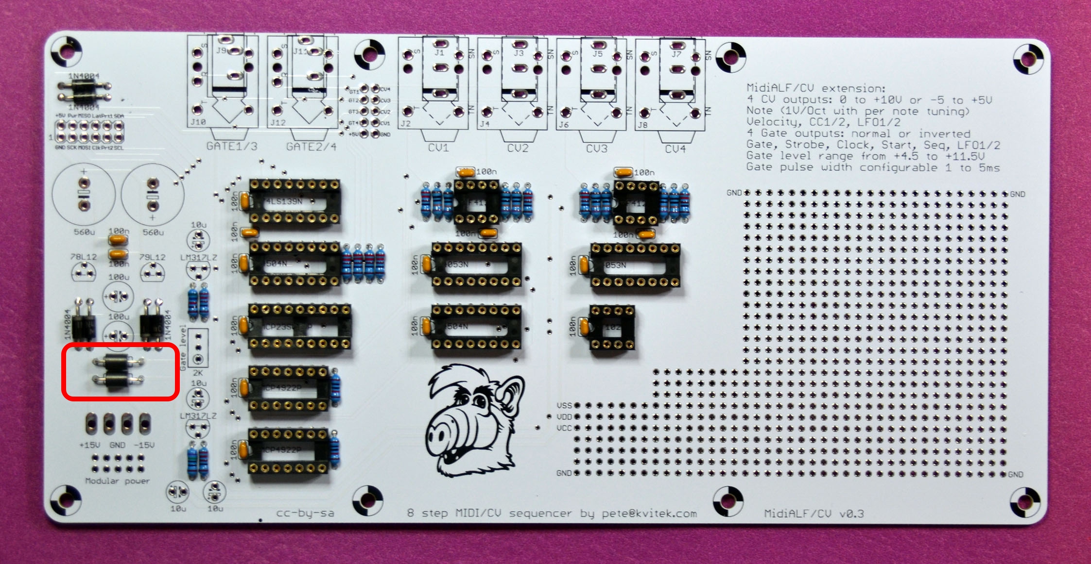
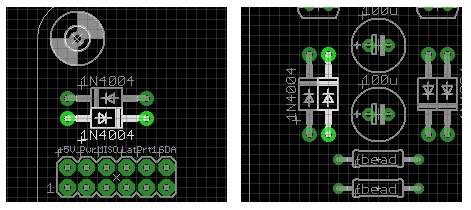
Add 6 x 1n4004 diodes:
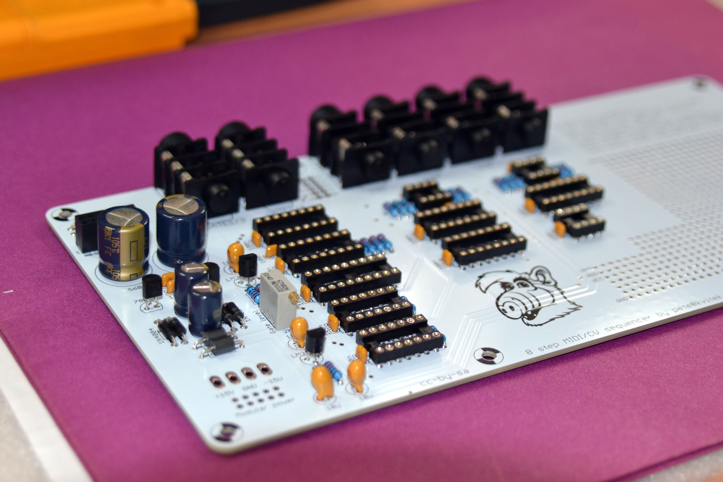
Add IC sockets. Note that the notch should be pointed to the left.
- 1 x 18 pin DIP
- 5 x 16 pin DIP
- 2 x 14 pin DIP
- 3 x 8 pin DIP
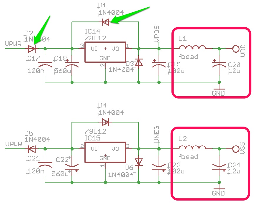
Add 2 x ferrite beads:
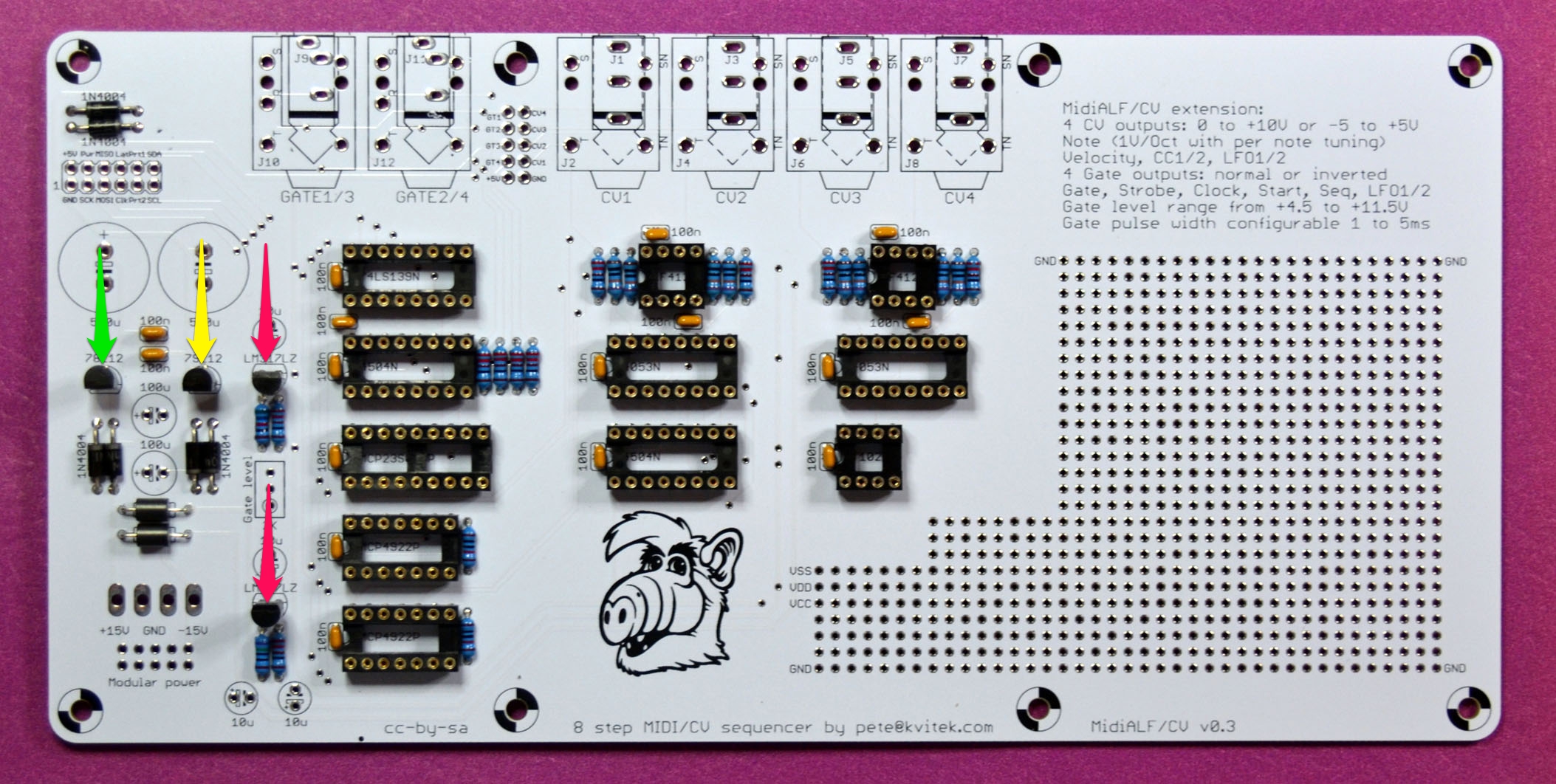
Add voltage regulators:
- 1 x 78L12
- 1 x 79L12
- 2 x LM317LZ
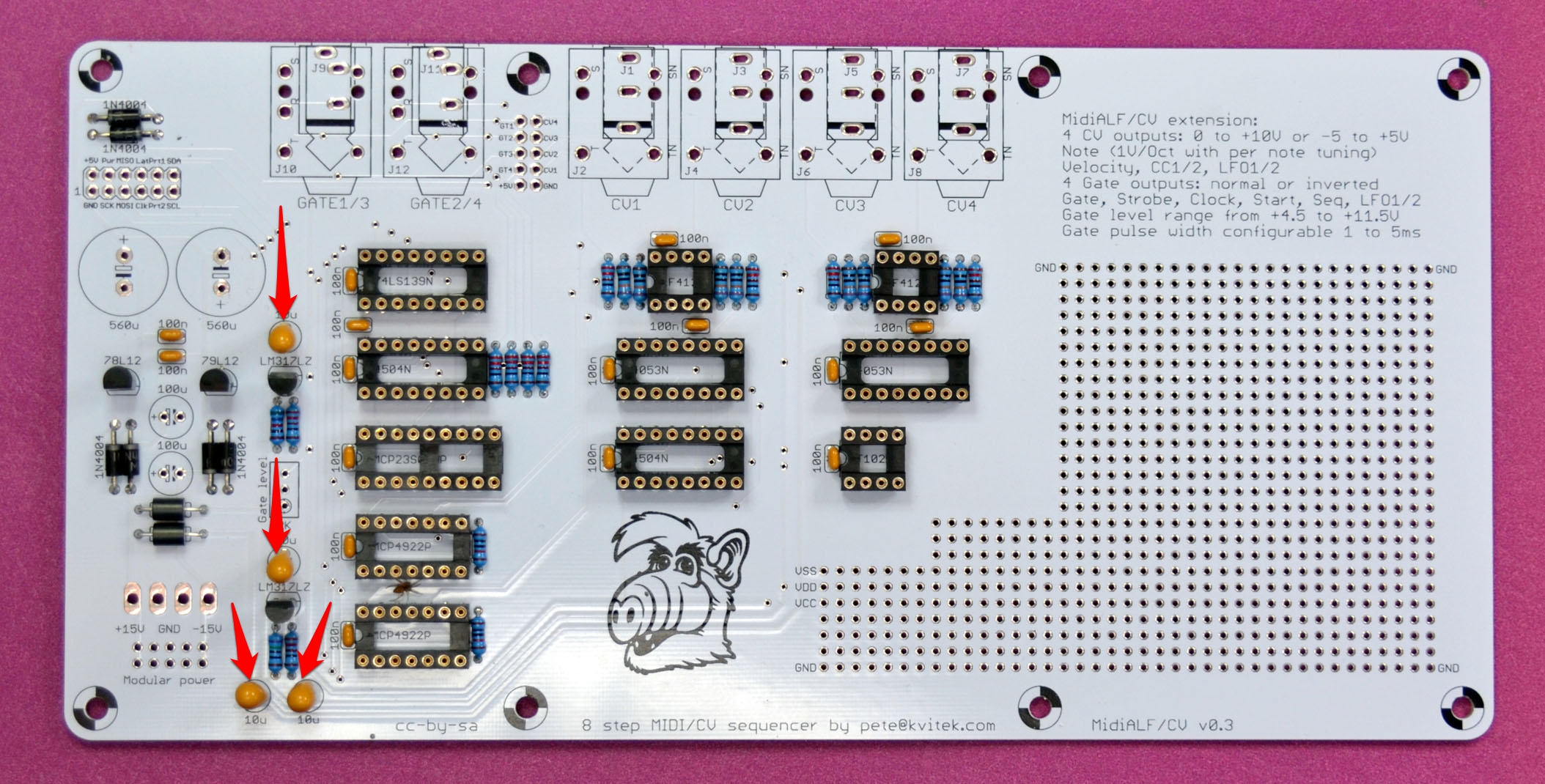
Add 4 x 10u tantalum capacitors:
Add 2 x 100u 16V electrolytic capacitors:
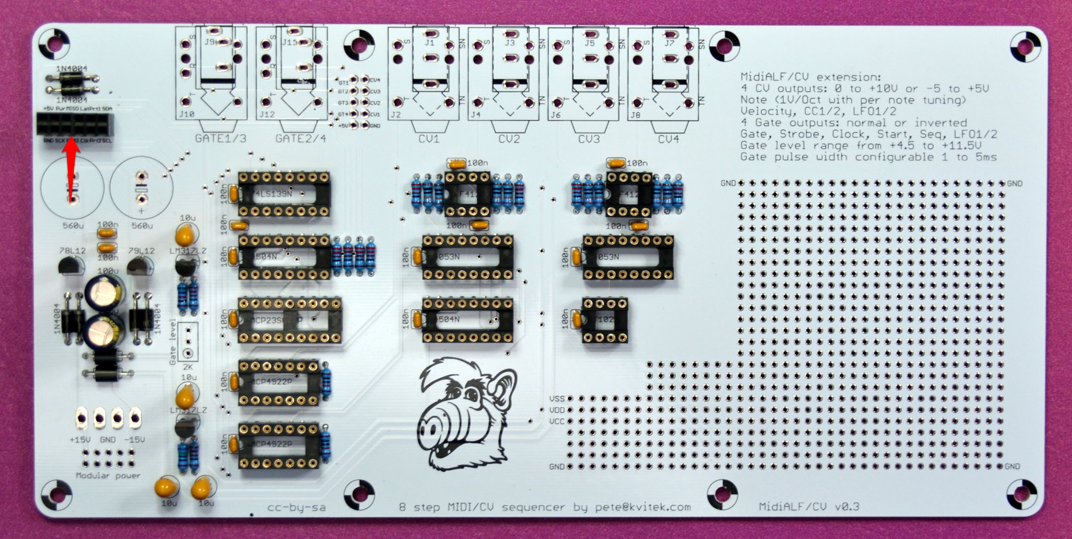
Add 6 x 2 female connector header. You can use more common 5×2 connector since rightmost two pins are not used.
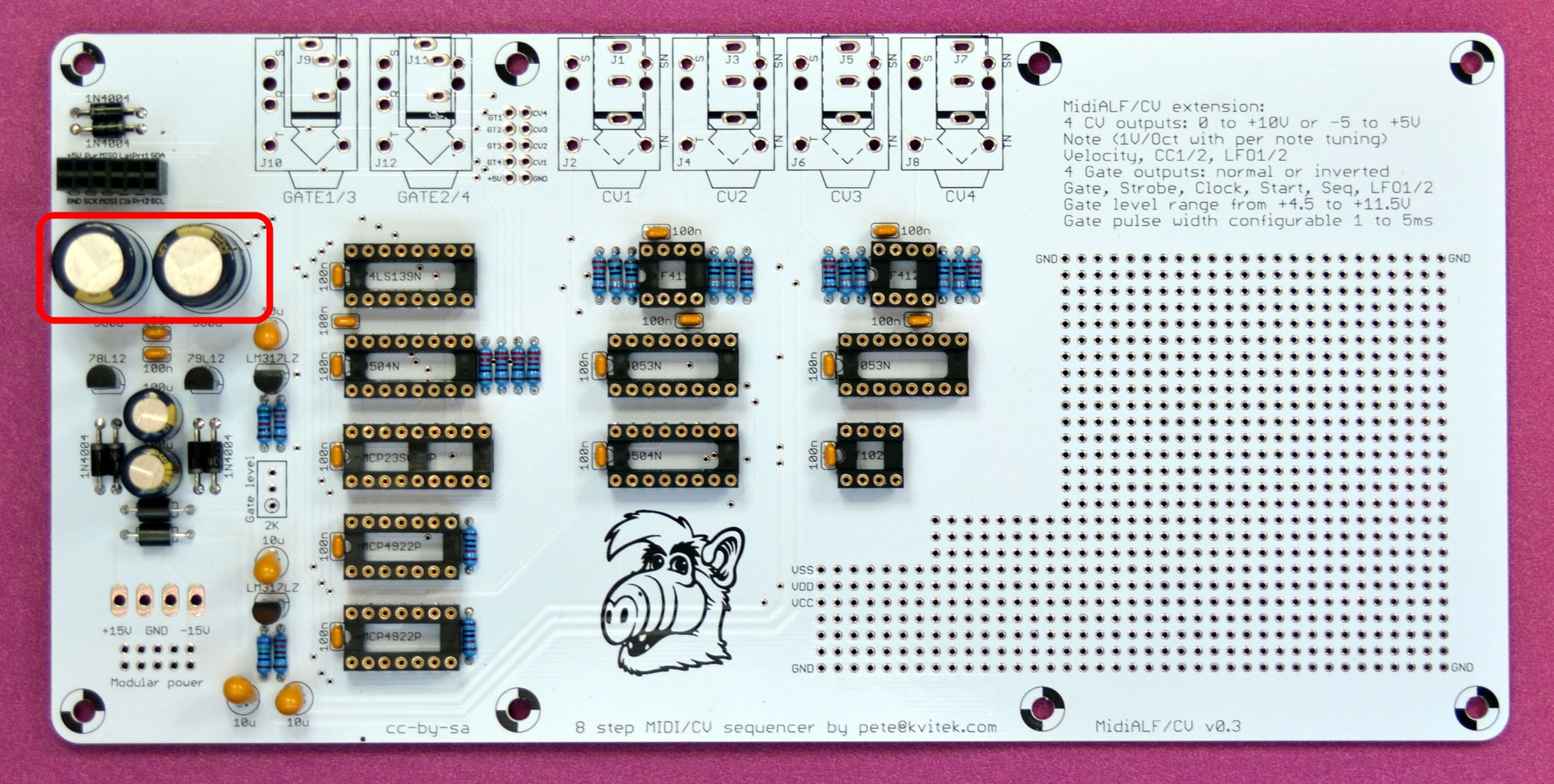
Add 2 x 560u 25V electrolytic capacitors. These should not be higher than 20mm if you’re using standard 7/8″ stand offs to sandwich the boards.
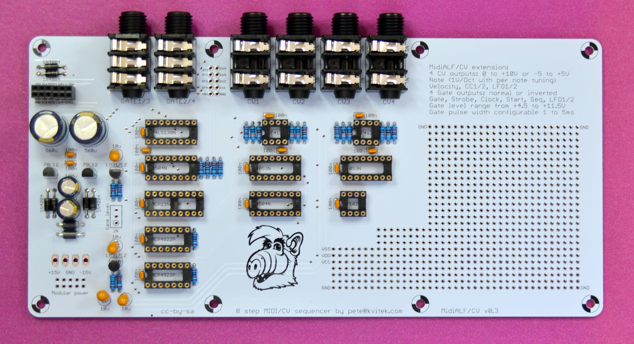
Add 2 x stereo and 4 x mono connectors. The board layout supports both 3.5mm and 1/4″ parts.
Add 2K trim pot:
Finished MidiALF/CV extension board:
Connect MidiALF/CV extension board to the main board using 2×5 extension headers.
Use trim pot to set desired gate level. If you don’t have oscilloscope to check the voltage you may set sequence note lengths to be longer than sequence step and measure gate output with regular voltmeter.
Powering MidiALF/CV from your modular system.

Pingback: MidiALF/CV info, schematics and docs published | MidiSizer
Are these boards available?
not yet, i’m ordering production run next week.
Hi Peter, are these boards ready (midi to cv)? If so, I’d like to order one, please send invoice when ready (shipping to Australia)
Yes, they are shipping. Please send me the email address to send the PayPal invoice to… see the Ordering MidiALF section.
Invoice sent.
done buddy, thx 😉
Hi Pete, you say the power supply should be 16VAC, but i think it has to be 16VDC because the DC-DC converter handles DC only? also, it seems a much higher voltage is possible, up to 24V?
can you confirm?
It has to be 16VAC since CV board will use it to create both positive and negative DC voltage using half wave rectifiers. The main pcb will only use positive half to regulate it down to 5VDC.
ok thanks … do you know how much current the MidiALF + CV extension draws to decide which adapter to get?
Depending on how current hungry your LCD is, MidiALF board could take from 130 to 250mA. Since you’ll be using unregulated 16VAC power supply, I recommend you to get the one capable of delivering 500 or 1000mA. I;m using this one: https://www.jameco.com/webapp/wcs/stores/servlet/ProductDisplay?langId=-1&storeId=10001&catalogId=10001&productId=100108
ok, i bought this 16VAC PSU and exchanged the 7805 regulator for the murata one, plus deinstalled the MIDI in/out LED’s plus their resistors – then i plugged it in, but MidiALF doesn’t boot anymore the screen is full of blocks, all led’s are on and the atmega gets very hot… i re-checked all the voltages on the board at the points given in the MidiALF construction guide and there is 5V everywhere as recommended. i tested with and without CV board connected.
any idea what might have gone wrong?
This does not sound good. I’d remove all ICs and check for shorts. If none found, insert Atmega, make sure it is oriented correctly. If it’s still hot, it might be fried.
I had exactly the same problem as Gerhard, and found that this can be resolved by either going for a somewhat higher voltage PSU (18VAC, say), or increasing the value of C3 (to 1000 uF, for example).
Hi Pete. If I power the MidiAlf/ CV-board from my modular PSU (+12v/ -12V), will the MidiAlf mainboard be powered as well? Or do I have to power it seperately? I have changed the power reg 7805 on the mainboard to the switching one.
Lars, please check notes at the end of “Building MidiALF/CV” section — I’ve added some notes there https://midisizer.com/midialf/midialfcv-extension-board/
Just did, great info, thanks. But will +12/-12 v be sufficient? I have a 16 v ac adapter, but would like to keep things as simple and compact as possible.
Yup, MidiALF’s native board power is +-12V
Guess the answer to my question is yes, as the v-regs on the cv-board are +12/ -12 volts…
Hi Peter,
I can’t find the 5V regulator (part number : OKI-78SR-5/1.5-W36H-C), but I can buy a LM1084 (Vin up to 25V, 5v output , 5A). I think it could be a good replacement. Do you think I can use it ?
MidiAlf finished ( Killer sequencer, I love it), now working on the cv board
Thank you
You might need pretty hefty heatsink for LM1084 to not overheat.
any boards left?
yes
Does this output in HZ/V scale for synths like Yamaha CS series or Korg MS?
You can set CV for every MIDI note separately, so you can drive Hz/V synths. However, there is no dedicated Hz/V mode.
That’s great!
Hello Pete,
I’ve finished the Midialf+cv , it had worked for ten minutes and after a big mistake (of me) , certainly a shortcut, no more cv, no more gates…(midi works correctly)
I’m trying to test the cv/gate pcb, but honestly I have really no idea, no signal at the input of the 2 opamps (LF412)…wich component could be the most sensitive to a shorcut ?
thank you in advance
Fabien
It really depends on where the short happened. What did you short ?
Start probing DACs MOSI and SCK signals, there should be some pulses there, check VREF, it should be +5V, check DAC outputs.
Hello, any places where to buy the EXC-ELSA35 ? Impossible to find it !
Any other ferrite bead of the similar size will work there.
Hum, ok not specials specifications needed ?
Is this one working ?
http://ca.mouser.com/ProductDetail/Murata-Electronics/BL01RN1A1F1J/?qs=sGAEpiMZZMtdyQheitOmRQ7zPkuBbGopFxejPEX%252bQMY%3d
Thanks for your answer !
Bye
Yep, that should work.
Hello, just finished my MidiAlf and cv-board, about to do some testing before I put it in an enclosure. So far I`ve come up with to problems; the SEL-led doesn`t light up when I push it, only when I turn power on, then it acts as it`s supposed to. Second, I have no output from gate one, the rest seems to be working fine. Any suggestions?
SEL LED — MidiALF firmware does not use it at this time, so it is only lit during power up sequence.
Gate1: chances are you have connectivity problem (cold joint or a short) on a connection from IC12 pin 2 to Gate1 out.
Thank you for helping out, I had a bad wire, changed it, and now it’s up and running! Great fun and an excellent machine!
Hi Pete – would a midialf with CV board work as a live MIDI to CV converter for live incoming signals from the MIDI in port?
Absolutely! MidiALF/CV is actually a pretty decent MIDI2CV converter.
Hi Pete, and Grats for this new add-on that looks promising ! I didn’t find anything else for 47p capacitors than ref. 81-RCE5C1H470J0A2H3B on Mouser. Is this fine?
Yes, this part is fine.
cool, thanks Pete for your return.
Pete, if I want to power this from modular power, is there any harm in installing the components ” outside of the pink rectangles? I bought all the parts anyway, may as well install them in case I want to power the device from the 2.1mm jack sometime, assuming there’s no technical reason why I shouldn’t.
…obviously, the D1, D2 diodes have to be replaced with jumpers to use modular power…
I’m not sure how voltage regs will behave with input and output pins shorted with voltage applied, so don’t recommend this.
Hello Peter, I received yesterday the PCB, well packed, quickly soldered, I just miss a few components before testing it with my Midialf. Just to make sure everything is OK : you mention to solder 6 x 1N4004 but the Mouser SKU of your BOM is 1N4001s, that I ordered. Is this OK ?
1N4001/2/3/4 are all fine.
OK thanks, my expansion board is soldered and mounted, but now the midi-in LED is not lighting up anymore, and firmware upgrade from my 0.92 is stuck before the midi in LED steadily lit. Any ideas ?
Increasing interval between sysex buffers to 250ms.may help.
I used Elektron C6 and did set this interval to 250 ms. When launched the job, I waited like 2 minutes, and nothing happened, neither on the leds side, which scares me on the hardware side.
I juste tested again, I simply didn’t have selected the midi in & out ports on C6, now it’s ok, the 0.94 cv .syx was totally sent after a few minutes, but when I restart, midialf doesn’t boot anymore, the screen is full of blocks, all led’s are on, and I can’t reset the device. Since I plugged the expansion board, midi-in led never works, and when I send midi data to midialf, strangely midi out led blinks instead of its neighbour. Even the Midialf alone, without CV board, has the same behaviour.
MIDI IN and OUT LEDs are not functional when CV board is connected — their ports are used to communicate with the expansion board. You may want to temporarily disconnect CV board and reload the firmware sysex watching the LEDs behavior.
OK cool, I managed indeed to upgrade midialf with expansion board disconnected, and now it can send via gate & CV. But my LEDs still seem buggy. Is it normal that, even when sequence is stopped, midi out led is always on, and midi in is always off, sequence playing or not ?
Midi LEDs show serial communication between main board and CV board and are meaningless on the CV build.
Hi Peter,
after a long time i managed to finish the CV board v3.
I removed the MIDI LEDs and the resistors for those, swapped the 7805 for the recommended OKI regulator, swapped the capacitors and fired up the board with my old power supply, all fine so far but very underpowered. After reading that it is now necessary to use a 16V AC power supply i bought one, plugged in and everything was lit and the CV Alf stopped working. Now i am a bit lost about where to look what may be the issue here as the built looks ok…
I’d temporarily disconnect CV board, remove all the ICs from the main board, and make sure that the +5V voltage on the main board is correct. Then i’ll insert main board IC’s back and check if it works, Then remove all the ICs from the CV board, connecto it and verify +12 -12V voltages, etc.
Ok, removed chips and get a clean 21,8 V on every point on the mainboard when the 16 V AC PS is plugged in. Looks like Mouser sent me a defective converter or a wrong part, cannot determine this as i never have used this type before. And at least the ATMega has met his ancestors. I tried to hook up my USBASP programmer and this stated that no device is answering…now i can only guess what else has been fried. A bit frustrating as it took nearly 5 months to get the converter from Mouser. And i measured the AC output of the PS with nice 17,8 V…this sucks.
Oh… i’m really sorry to hear that. I will update build instructions to suggest people to remove ICs and test VCC after PSU re-work.
Fried ICs are easy to replace. I’d be more worried about LCD — if it’s fried, i’d recommend cutting off its connector and then desoldering its pins one by one.
I used an oldschool crystal LCD and it looks like its still alive, if not than it is a good excuse to put in a new one…i still wonder if the 17,8 V of the AC powersupply have fried to converter first.
Ok, here we go: clean 4,92 V on the VCC rail and on the mainboard, 11,8v on the power rail of th CV board. This looks better…now to the bad news: ATMega is absolutely dead and the LCD shows only backlight. So now my question: is the LCD driven by the ATMega and this is normal or should i prepare myself for the worst and replace the LCD too ?
LCD is certainly driven by the ATMega, and if the latter is fried, the LCD wont show characters. However, LCD controller could also be fried. One way to test it is to turn LCD Trim all the way in one or the other direction. If at some point you see one like of box characters, the LCD controller may be still functioning: LCD controller fills up the top row with boxes if it receives no communication from host CPU.
If you have to replace LCD and you don’t have a decent re-work station or solder sucker tool, i’d recommend cutting the LCD board next to the connector, then cutting the connector and removing connector header pins one by one.
As i had an ATMega for another project lying around, i managed to replace it and flashed the firmware. Sequencer and LEDs are running, as far as i can tell, because well the display shows nothing but backlight and here and there some boxes, but however i turn the trimmer it doesn’t really change or work. A quick measure of the connectors shows that it should…well it’s time to pick up my Dremel and cut this bitch out. I guess now its time for some patience while desoldering it.
Hi, I’m selling my MidiAlf, with CV expansion board, all mounted, and with a DIY plexi/wood box. It’s in France currently. Anyone interested ?
nuclearsound.
are you still selling your MidiAlf?
yeah, boards are still available
Nop, finally still using this beast 🙂 kvitekp, feel free to delete my post !
Is it possible to use the MidiAlf as a sequencer and a Midi to CV interface at the same time? So that e. g. two gates/cv-outs would be used to play a sequence and the other two gate/cv-pairs would translate a seperate incoming midi signal ? Thanks.
No, current firmware does not support this: midi2cv converter inside MidiALF is driven by MidiALF sequencer.
I see. Thanks for the answer. So my feature request would be a midi-through page for the cv/gate board. I don’t know if the code would, though.
hello pete !! which is the positive pole in the pcb for leds bottom mec and sequence ? i am in the middle build !!!!
All LEDs have cathode on the ground, which is at the left for the Side LEDs and top for the Step LEDs.
Very cool, the nicest MIDI to VC thingy I could find! The modification doesn’t make ALF loose any midi features, right?
Yeah, all the MidiALF MIDI functionality is still available, CV extensions just makes CV and GATE signals available four you modular or classic synths.
hello Pete!! here i am again ..! i want to order another midialf cv v.04 kit plus an ic preprogramed. send me the invoice to my mail. i will send you some pictures of my work soon.. greatings from argentina!!
Hey Diego, i’m not sure what your email is, so please email me at the address specified at the ordering page, thank you!
Can the MidiAlf run a sequence with note and gate and as the same time run LFOs from the remaining cv/gate outputs ?
yes
Hi ! I finished building the CV board but I’m having some issues. First nothing seems to work, no cv seems to be sent to the modular/ But then when I probe the pins I find that on the connection between the Midialf and the CV board I get +5V and at the cv outs I also have the +5V so everything seems fine there. The issue is that the gate outs seem to send a constant voltage, determined by the gate trimmer. It never goes off even when all the steps are muted. Furthermore the CV1 Note sends a constant -4,7V regardless of the note being played. I reflowed the whole board without success 😦
You’ll need an oscilloscope to trace the CV1 and gate signals and figure out where it gets lots. CV signals start at the DAC. Gate signals start at MCU. Both are in range of 0-5V signals initially.
Thanks but could you be more specific ? What am I looking for exactly ? Sorry it’s all a bit new to me 🙂
Hello, I just bought a second hand MidiALF and would like to build a case around it. Is there a reference file with values/holes that I can base on available?
Yes there is. Also, there are proven designs for laser cut 3mm acrylic cases for both MIDI only and MIDI/CV variants. Please send email me at the address specified at the ordering page to get the design files.
Hi,
Any chance of seeing a Hz/V version coming out at some point?
(I have old Yamaha and Korg gear…)
Thanks!
You can use note tuning to achieve Hz/V. Yamaha CS series and Korg MS-20 are known to work well with it.