MidiThru is an active MIDI splitter useful for distributing MIDI clock and powering MIDI devices through MIDI connector.
There are two variants available: original 1 to 5 and MidiThru x2 which is two 1 to 5 MidiThru combined.
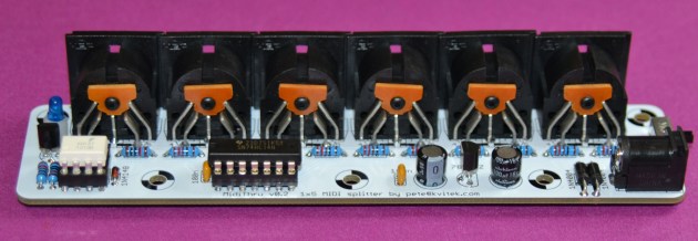

Both are easy to build, inexpensive and very useful MIDI gadgets. A must have for any non trivial MIDI setup.

Pingback: MidiThru | Futuredraht
Hey Peter,
I love this kit, but do you have a solution for a midi merge situation? It appears that this is a 1 to 5 out but I would love to construct a 4, or 5 into 1 output format. I can’t seem to locate any projects online, maybe you know of a source for a DIY kit? thanks!
I have 2 x INs x 2 OUTs project in works, it’s not published yet. I doubt you can find DIY 4 -> 1 merger solution.
Are you near publishing that merger solution?
The hardware is ready, however the firmware is still not finished. Do you have any specific requirements for it?
Hello, what dimension is the midi THRU x2? thank you in advance
PDF board outline in 1:1 scale is available here: https://midisizer.files.wordpress.com/2017/12/midithru_x21.pdf
This is a nice and compact solution, good work! Will it be difficult for a beginner to build this with just 3 MIDI outs? Will I just have to drop 2 of the MIDI out connectors and their corresponding resistors and inv Hex Schmitt Triggers? Or would I have to change the supply voltage or something?
Yeah, MidiThru is perfect beginners project. You can leave out MIDI OUT connectors and corresponding 220R resistors. Triggers are integral, you cannot drop them.
Thanks for your instant reply! Excuse my slurry wording, sure the triggers are part of the IC which I just have to leave unconnected…
Are you still shipping the schematics? What would be the shipping to Brazil? Do you have the BOM?
Yeah, MidiThru is still available. PCB cost is $15, shipping internationally is $10. BOM is available here: https://docs.google.com/spreadsheets/d/1eJMj-EN9_QR7UoGnr4wrilML-53yx9uB1r04tnlesYk/edit#gid=1
Hi peter ,
I would like to order 2 midi thru boards .
Can you sent me an invoice
Cheers jeroen
Sure, please send me an email to the address specified at the order page.
Hey, would this work for note data? I’d like to utilize more midi synths with out buying equally more midi keyboards (I already have one nice one I paid to much for to begin with). I’m already planning on making one for my drum machines, but I’d love to make 2 if it works for note data as well!
MidiThru works equally well for all MIDI data, including note events.
…to anyone considering ordering this board and building the midi thru — the components are easy to find and inexpensive, its easy to build, and the finished unit works flawlessly. Highly recommended!
Agreed! This was my first build where I just bought the PCB and sourced all the parts myself so I was a bit out of my comfort zone but I had absolutely no problem getting this up and running in about an hour tonight! Thanks Peter! Excellent work!
Thank you, Paul!
Can you build one and send it completed ?
Yeah, please email me at the address specified on the ordering page.
Do you sell cases for the PCB too?
Unfortunately, no. However, there is an acrylic case plans floating around at Mutable Instruments forums.
Any plans to produce this case? I’d love to build this but I’m terrible with cases and don’t have access to a laser cutter for the acrylic. The cases on your other kits look great! Thanks!
At this point i don’t have a case for MidiThru. Even if i’ll come up with one, it’s not going to be a full box case. The plan is to use a “sandwich” case with only top and bottom plates.
This is correct: only LM78L05 needs to be reversed due to an error on the silk screen. Build documentation clearly states this.
That sounds awesome! Thanks!
Hi Pete, do you do combined shipping? If i want 3 pcb’s. Thank you
Christian
Of course! If your order three PCB you only pay shipping once.
Thanks Pete. I’ll get back to you soon
hello ,
How to buy from france?
Please contact me using the email address specified at the ordering page: https://midisizer.com/midithru/#ordering
Do you think the existing regulator and the first trigger could drive 20 outs of I just continued to attach triggers in parallel? I only ask because you might have the network values worked out already, save me some time and brain power 🙂
I did not try this, however it should be possible, because connecting 4 inputs to 74LS output is not a problem, and 78L05 has enough current capability to power 5 ICs.
Hi Pete
just a smal hint: the transistor 2N3904 isnt just mirrored at the PCB’s, its also mirrored in the schematics 😉
my fault…. plz ignore/delete 😀
This midithru will be my first attempt at building a real through hole project, I’ve practiced my soldering technique on a handful of beginner soldering kits. Any suggestion on which components to install first? I plan in building Midirex after this .
Start with resistors and diodes first, then capacitors, then IC sockets, then transistors and voltage regulator. Then proceed to DC connector and switch. Finally install MIDI connectors. Generally, you always want to install smallest components first. You can use MidiGAL build guide as a reference since it has similar components: https://midisizer.com/midigal/building-midigal/
Thanks for the tip! — Just received my parts order from digikey — so I’m excited to build it this weekend.
Hey,
Just wondering, why would you put SN74LS14N (which is an inverter) to revert midi in and then revert it again afterward?
I don’t really get this part logicwise, eventhough I guess it’s about electronical matter that I don’t really understand. Could we only use an AOP in all midi input ?
Regards,
7414 is a classic Schmitt trigger IC and it has inverting output which needs to be inverted again. What is AOP?
I guess AOP is the french word for operational amplifier. I do understand why do you need the schmitt trigger, I was thinking that it was only an inverter.
Anyway thanks for the schematic, I think I will have the use for it very soon :p!
Yann
Hi,
I’m interested into building a thrubox kit but I would better have it 1->8 minimum.
Ive read I could use 2x hexinverter To do so.
Could I somehow make it with your pcb ?
Do you have any schematics or pcb files to make it happen ?
R
With two hex invertors you can build 1->5+6=11 MIDI Thru device. Just replicate repeated output ports section at the bottom of https://midisizer.files.wordpress.com/2013/01/midithru1.pdf
You can probably use MidiThru X2 PCB, cut some traces and add some jumpers to build 1->11 MIDIThru, but it would be pretty messy.
Hi!
I’m trying to build this midi thru schematic as a 1×10 thru 19″ rack, using an extra schmitt trigger to repeat the output ports. I’ve collected all the parts and built everything up on a breadboard to test, but I can’t seem to get it to work. So far no midi has come from the input to the output, and the LED has been turning on and off irregularly, also changing in light intensity.
I’ve checked all the connections multiple times, they should be fine. My electronics knowledge is very basic, I try to learn a lot along the way. What might be the issue here?
I left out the voltage regulator and the three capacitors and two diodes within that part of the circuit, and used a generic USB power supply, a 5V 1A iPhone charger. Could that be the problem?
Also, I’ve left the remaining in and out ports on the inverter unconnected, just to test one output first. But that should be fine right?
Also, what parts break easily, and how can I test them? I’ve already replaced the optocoupler because I thought that was the problem, but it did not make any difference.
I hope you can help me out!
It’s not possible to guess the problem you are having. You need to get an oscilloscope and and probe the signal from the beginning to the end and see where it breaks.
Fist check the optocoupler output and verify that the short negative pulses are present there when MIDI events are received. Then follow to Smidtt triggers inputs and outputs.
You can leave power supply parts out, however, it’s highly recommended to have a 100n across trigger IC volteage supply pins.
I recreated the project on breadboard using the schematics provided. It didn’t work untill i looked up the 74LS14N data sheet and found out the IC needs vcc to pin 14 and gnd on pin 7. When i added this, everything suddenly worked like a charm 😀 Is that part missing from the schematics, or am i missing something?
Thanks for supplying the schematics for free by the way! My next step is transfering everything to prototyping board, 3D printing an enclosure, lasercutting a 19inch rack plate, and having everything mounted in the studio rack as part of a large midi patchbay. Loving this project!
Modern schematic capture CAD tools typically provide IC power connection automatically. This is why you don’t see it explicitly specified on the schematics.
Hi,
What is the “negligible” propagation delay about ? Are we talking about something like 1 ms or something like nothing like in analog world ?
If I use the 2x version and connect one of the first row output in the second row input, how much delay would be added ?
Thanks
Typical 1N137 propagation delay is about 50ns, 74LS14 adds another 10ns. Even in the worst case the delay is < 100ns, so you can chain lots of them without any problems.
I’d bought the pcbs for this a long time ago and I thought I’d source the parts and build it up. I may have a different version or something as there’s one part I’m not sure about. The unit is not powering so I’m thinking it could be the power switch but it’s only a 4 pin rectangle on the pcb. Any info would be great or a build doc?
Cheers!
You can check the voltages before and after the switch to see if it’s working as expeceted. In any case you can just short the switch pins to bypass it.
Hi ! Is it possible to chain multiple original MidiThru with a single power supply ?
yes, there is a connector header on th pcb exactly for this purpose.
HI, i’m so sorry i can’t seem to find that header, where is it located on the pcb ?
Just wanted to say thank you, this is a great piece of gear, and it was a very straightforward build, even for a beginner like me!
Have you built a midi merger yet?
I did, but but not in the MidiThru format — it has display and knobs… the one in MidiThru X2 format is still in works.
Just a note in case anyone else is having the same problem as me:
The 100n across power pins (7 & 14) of the schmitt trigger IC is indeed critical. I hand wired this circuit and had problems with the module spitting out random/unpredictable MIDI data. After some (too much) trouble shooting I realized the obvious: I forgot the 100n cap. Works flawlessly now, awesome utility.
Thanks for sharing this schematic!
For those looking at powering this with a modular PSU:
The circuit draws about 4mA on the +5V rail using the components spec’d in the BOM. Tested in-circuit under normal MIDI through usage.
On the topic of an appropriate power supply, this one meets all the needs and has the added benefit of interchangeable blades for international compatibility.
Part info: CUI SMI12-9-VW-P5R
Digikey part #: 102-SMI12-9-VW-P5R-ND
Link: https://www.digikey.com/en/products/detail/cui-inc/SMI12-9-VW-P5R/12720807
Slightly cheaper North America only adapter is as follows
Part info: CUI SWI15-9-N-P5
Digikey part #: 102-4671-ND
Link: https://www.digikey.com/en/products/detail/cui-inc/SWI15-9-N-P5/7399207
74LS14N or 74HC14N?
Schematic says 74LS14N the bom says 74HC14N. Does this matter?
Sorry if this is something obvious, i usualy only put toghether kits.
You can use any 74xx14, it does not really matter.