Midi2CV Mk2 is a DIY embeddable MIDI to 4 x CV/Gate converter with extensive configuration options and extra modulation sources (LFO and AHDSR EG).

Specifications
POWER SUPPLY
- +-12V or +-15V, Euro or MOTM power connector
- 50mA@+15V, 10mA@-15V
OUTPUT
- 4 x CV channels, each could be 0+5V, 0+10V or -5+5V, configurable by jumpers
- 4 x Gate channels, 0+5V, 0+7V or 0+10V, configurable by a jumper
MIDI IN LED
- optional MIDI IN LED, blinks when receiving MIDI events
GATE LED
- optional GATE LED, lit when a note is on
MIDI IN
- MIDI IN connector
MIDI OUT
- optional MIDI OUT connector, mirrors MIDI IN
LEARN SWITCH
- hold down during power up to enter firmware update mode via MIDI
- hold down while receiving a note to learn MIDI Channel (v2.03+)
- hold down while receiving control change to learn control CV parameter
- hold down while moving pitch wheel up/down to turn note tuning mode on and off
- hold down for 10 sec while the device is idle to reset the device to default settings
- hold down and release in less than 5 seconds to reboot the device
WebMIDI configuration and firmware updates (v3.50+)
Navigate your browser to the Midi2CV Mk2 configuration page and select MIDI port names your Midi2CV Mk2 is connected to. Note that you need the two way connection: computer MIDI interface MIDI OUT port should be connected to Midi2CV MIDI IN, and Midi2CV MIDI OUT port should be connected to computer’s MIDI IN port.
Using Midi2CV Mk2 configuration you can do the following:
- query currently installed firmware version
- update firmware to the latest version
- view and change all device configuration settings
- view and change all LFO and EG parameters
- send and receive device note pitch tuning data
Important: at this time only Chrome and Edge are known to support WebMIDI reliably. Firefox and Opera may work too.
On-board switches
SW1-4 specify default base MIDI channel
- MONO, DUO and POLY modes use the base channel
- QUAD mode uses base channel, base channel +1, +2 and +3
1234 ch     1234 ch
.... 01     ...X 09
X... 02     X..X 10
.X.. 03     .X.X 11
XX.. 04     XX.X 12
..X. 05     ..XX 13
X.X. 06     X.XX 14
.XX. 07     .XXX 15
XXX. 08     XXXX 16
SW5-6 specify operation mode:
- MONO — classic monophonic mode with last note priority
CV: note, velocity, after touch, control
Gate: gate, strobe, start, clock - DUO — classic duophonic mode
CV: note1, note2, velocity, aftertouch
Gate: gate, strobe, start, clock - QUAD — four pitch CVs on adjacent MIDI channels
CV: note1, note2, note3, note4
Gate: gate1, gate2, gate3, gate4 - POLY — true polyphonic voice allocation
CV: note1, note2, note3, note4
Gate: gate1, gate2, gate3, gate4
56 Mode
.. mono
X. duo
.X quad
XX poly
Note CV: 1V/Oct pitch CV with optional micro tuning: every note can be set to output any CV level within selected output range. Can be used for Hz/V, alternate tuning schemes, or to correct VCO tracking imperfections. Note tuning is configured using special operation mode, and could be saved, restored or loaded via a sysex message from a computer.
Velocity CV: linear by default, however, you can choose to adjust velocity response curve making it softer, harder or wider:
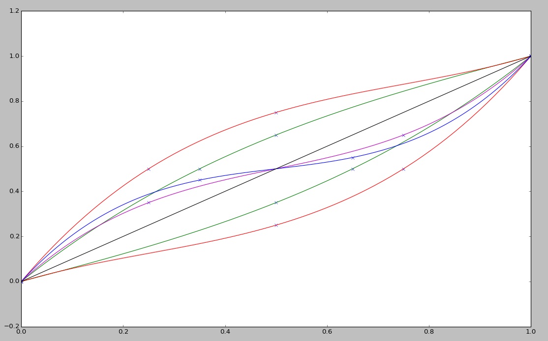
After touch CV: linear by default, however, you can choose to adjust the after touch response curve making it softer, harder or wider, similar to velocity CV above.
Control CV: by default, this CV tracks CC 1 (Modulation Wheel) value, however, it could be set to track any CC from 1 to 119. Control change number can be “learned” on the fly: hold down the LEARN switch and turn/click the desired control knob/button.
Gate: goes high when a key is down, low when no keys are down. If “strobe gate” option is in effect, gate signal is pulled down for the duration of the strobe every time a key is pressed while some other key is down. This allows envelopes to re-trigger for synths that don’t have Strobe input.
Strobe: goes down for 1 to 5 ms, occurs each time a key is pressed. Strobe length and polarity are configurable by sending a sysex message and the setting is persisted in EEPROM.
Start: goes high when MIDI Start/Continue message is received and down when MIDI Stop message is received.
Clock: goes down for 1 to 5ms each time MIDI clock message is received, could be divided down to 32 triplet, 32th note, 16 triplet, 16th note, 8th note triplet, etc. all the way to 2 bar note. Division factor is configurable by a sysex and the setting is persisted in EEPROM.
MIDI Channel
On-board switches SW1-4 specify the default MIDI channel. Midi2CV Mk2 uses this channel when it is first started or is reset to default settings. You can change Midi2CV Mk2 MIDI channel by changing these switches or “learning” it from a note played while holding down the LEARN switch. The “learned” MIDI channel will be in effect until the device is reset, in which case the default MIDI Channel specified by DIP switches will be used.
LFO and EG
Starting with firmware version 2.0, Midi2CV Mk2 provides two extra modulation sources: LFO and AHDSR EG which can be assigned to any CV output. These modulation sources are controlled by MIDI CC commands sent from an external MIDI controller connected to MIDI IN.
LFO specifications:
- frequency: 0.016-50Hz (free running)
- synced to MIDI clock rates: 32 bars – 64th triplet
- basic waveshapes: sine, sweep, lumps, spike, sine3, sine5, triangle, ramp up, ramp down, square, random sample&hold, random lines, noise
- phase distortion waveshaper
- wave steppyness
- free running or reset on note on
- fade in 0 – 10sec or 64th triplet – 32 bars if synced
- bipolar or unipolar
- amplitude control
EG specifications:
- segments: Attack, Hold, Decay, Sustain, Release
- segment duration: 0-15sec
- segment shape: linear, expo, sine
- legato retrigger: on / off
- MIDI Clock retrigger: 1/32T – 2bars
- auto gate control – 0-15sec (similar to MS-20 EG)
- looping: off, gated, auto
- inverted: on/off
- amplitude control
In looping mode EG can be used as a fancy LFO with the shape composed by four linear, exponential or sinusoidal segments with the duration specified by Attack, Hold, Decay, Sustain and Release controls.
Software pitch bend
Starting with firmware v3.10, Midi2CV Mk2 supports software pitch bend: note CV is affected by MIDI Pitch Bend events according to pitch bend range in semitones set by the 0Bh sysex command. If pitch bend range is set to 0, software pitch bend is effectively disabled. The pitch bend range setting does not affect hardware Pitch Bend CV.
Polyphonic port mapping
When polyphonic port mapping is enabled and the device is in MONO mode, all CV/Gate outputs will have the same note info. This enables a unison mode in polyphonic setups where each CV/Gate is permanently connected to a voice circuitry. In DUO mode polyphonic port mapping allows duophonic unison mode: single note info is sent to all CV/Gate outputs but when two notes are played, there are two pairs of different CV/Gate outputs.
Note CV tuning
The default note CV tuning is 1V/Oct for output range 0-10V and -5+5V ranges, and 0.5V/Oct for 0-5V range.
To enable note CV tuning mode, hold down LEARN switch and move Pitchbend wheel up, then release LEARN switch and return Pitchbend wheel to neutral.
To disable note CV tuning mode, hold down LEARN switch and move the Pitchbend wheel down, then release LEARN switch and return Pitchbend wheel to neutral.
While note tuning mode is in effect, hold down a key and use the pitch wheel to adjust the note’s pitch. Release the key to remember the note’s pitch.
You can also use Control Change messages to reset, increment/decrement and interpolate note tuning, see the CC table below.
Firmware update
Midi2CV firmware update steps:
- Connect your MIDI interface output to Midi2CV MIDI IN
- Power on Midi2CV while holding down the LEARN switch. LEDs will blink shortly then MIDI IN LED will stay steadily lit. Alternatively, you can request firmware update by sending ‘request_firmware_update.syx’ file to MIDI IN.
- Send firmware update sysex file (*.syx) to your MIDI interface port with 250ms delay between sysex buffers. Elektron’s C6 works great on OS X and Windows. Classic MIDI-OX is also good on Windows. MIDI LED will be blinking while firmware sysex is being received. On successful update, LEDs will blink 3 times one after another. On error, both LEDs will blink together 5 times.
Starting with firmware version 1.14 you can request firmware update without using LEARN switch by sending REQUEST ACTION sysex 0x00 with modifier byte set to 0x01. This facilitates firmware updates for applications where LEARN switch is not present or is difficult to access.
Revision history
v.3.63 07/25/2026
- Added SYSEXCMD_MIDICHANNEL sysex command
- Fixed problem with the last tune table entry garbled after MIDI initiated firmware update.
v.3.62 07/21/2026
- Implemented LFO sync to MIDI Clock, affects both LFO and fade in rates
- Added device mode and channel to SysEx device status.
v.3.57 11/02/2023
- Optimized LFO/EG CC handling to prevent choking, thanks to Ben A.M.
- Reordered LFO shapes for convenience (most popular go first)
- Changed LFO fade in curve to be more gradual
v.3.55 09/16/2023
- Implemented damper pedal support (CC 64)
- Implemented UNISON4 and UNISON2 options for polyphonic setups
- Implemented Enable Soft MIDI THRU option
- Improved DAC precision at high notes
- If LEARN switch is pressed and released in less than 5 secs with no MIDI input reboot the device
- Revamped SysEx handling, added SYSEXCMD_DEVICESTATE and command modifiers in order to enable web page settings management.
- Fixed problem with note tuning wrapping up to the top when pitch bend is moved all the way down
- Optimized LFO and EG control change handling to prevent device choking on fast MIDI streams
v.3.42 10/27/2022
- Fixed subtle stability issue with gate output, thanks to Chris G.
- Fixed problem with release key retrigger that would retrigger just triggered note.
v.3.40 01/30/2022
- Replaced DUAL mode with classic DUOphonic mode. If you need old DUAL mode please consider using QUAD mode and strobe gates.
v.3.30 01/27/2022
- Replaced PitchBend CV with AfterTouch CV.
v.3.20 08/05/2021
- Fixed problem with note tuning introduced in previous update, thanks to GregC.
v3.10 05/19/2021
- Implemented software pitch bend support with configurable range of 0 to 12 semitones.
- Fixed probelms with MIDI channel number wrap around when base channel is set to 16 in DUAL or 14, 15, 16 in QUAD modes.
v3.00 11/30/2020
- Replaced DRUM mode with POLY mode that provides up to 4 channels of true polyphonic voice allocation.
- Re-worked MIDI I/O implementation eliminating jitter and minimizing soft MIDI Thru delay.
v2.03 6/24/2017
- Implemented MIDI Channel LEARN feature.
v2.02 5/23/2017
- Fixed problem with clock output generating clock at incorrect frequency after receiving MIDI Stop followed by MIDI Continue events. Thanks to Benjamin for reporting.
v2.01 3/8/2017
- Implemented more musical LFO fade in
v2.00 3/7/2017
- Added LFO and EG
v1.14 1/10/2017
- Set note CVs to C4 upon start or reset
- Added ability to request firmware update by sysex
v1.13 11/3/2016
- Added “strobe gate” option and sysex
v1.12 07/02/2015
- Added gate polarity option and sysex
v1.11 06/17/2015
- Fixed problems with All Notes Off handling
- Added strobe polarity option and sysex
- Added firmware version request sysex
v1.10 02/14/2015
- added Drum Mode
- changed Note Tuning mode activation to LEARN+PitchBend
- fixed nasty EEPROM initialization bug
DIY Resources
Bill of Materials: Midi2CV Mk2 BOM
Firmware: Midi2CV_Mk2_v363
Sysex files: Midi2CV_Mk2_v355_syx
Schematics: midi2cv_mk2
Firmware source code: midi2cv_mk2_300_src
Board outline (1:1 PDF): midi2cv_mk2

Ordering Midi2CV
To order Midi2CV, please send an email to pete at kvitek c o m specifying how many PCBs and pre-programmed MCUs you need, a country where to ship them, and an email address to send the PayPal invoice to.
Prices (US dollars):
Midi2CV PCB — $25
Pre-programmed ATMega328p — $10
2 x MCP4922 DAC ICs — $10
Shipping:
Continental USA — $5 (California residents add 8.75% tax)
Canada – $15
Europe – $20
Australia – $20
Please make sure your PayPal shipping address is correct!
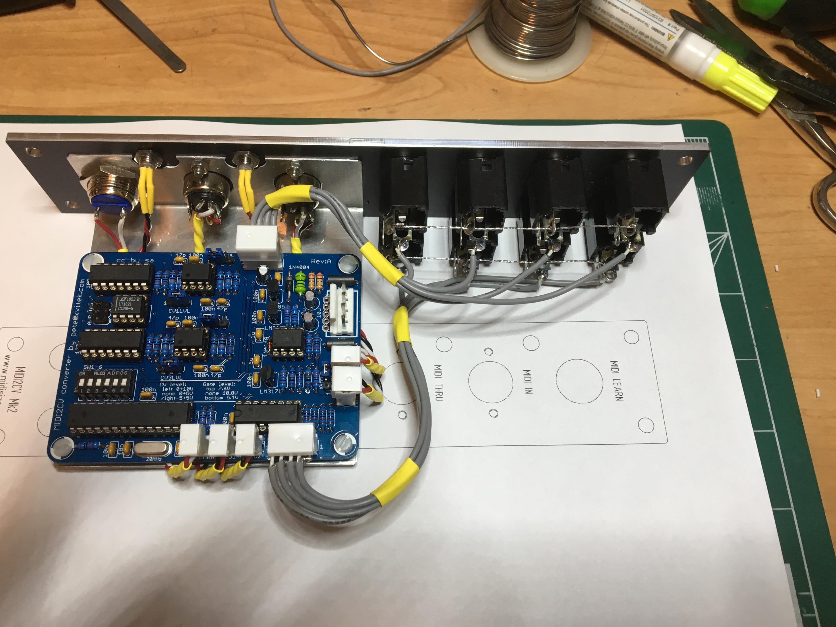
Midi2CV in 5U format
Parts
MIDI LEARN switch: E-Switch PV2S240NN — DigiKey, Mouser
DIN MIDI connectors: CUI Devices SD-50SN — DigiKey, Mouser
1/4″ connectors: Switchcraft 112AX — DigiKey, Mouser
MOTM
FrontPanel Express panel: 1U_MIDI2CV

MU
Vector format panel: Midi2CV_MU_panel
I have a few of these available for sale, please email me at the address specified on the ordering page.


Pingback: Midi2CV Mk2 is available! | MidiSizer
Nice, this looks very versatile! Are the CV outs buffered?
Sure, it uses a well known op amp circuit with 1K output protection resistor included in the feedback loop for better precision, see schematics.
Pete, I would like to order Midi2CV PCB — $25
Pre-programmed ATMega328p — $10
Thanks, Ed
Sure, Ed — please send an email to the address specified at the ordering page https://midisizer.com/midi2cv-mk2#ordering. Thanks!
Hi, where we can order ? Thanks
Here: https://midisizer.com/midi2cv-mk2/#ordering
That’s cool!
Any chance for a Midi to 16 CV &16 Gates?
Not at this time… what’s the application?
It is for an 808 clone but with 16 voice boards!
To make sound on 808 board you need 2 different voltages hit at the same time.
One is for Trigger and it is 5v and the other is for Velocity and it is from +5v and max +15v.
I need to control velocity for every step. So what i need is your module but with 32 outputs (16 CV & 16 Gates.)
Best Regards
Tilemachos
A bit tricky, but certainly doable: take 4 MIDI2CV Mk2s, run them in parallel in DRUM mode responding to different notes on the same MIDI channel split by MidiThru, build a simple divider to get -5V, and feed it to left side R14,R15,R27,R28.
Very nice job! Do you send PCBs to Brazil ? Thanks
Yeah, i send them all over the world. Never had a chance to send them to Brazil though 😉
hi, is there an option to use 8 midi CC’s for 0-5v output?
No, however you could easily add it yourself if you know a little C++. That would be 4 x CVs though.
What resolution is the MIDI to CV conversion please?
12 bits, see the DAC specs here: http://www.microchip.com/wwwproducts/Devices.aspx?product=MCP4922
Hello!
Can i use it with my vintage Korg MS20?
Can you ship to Russia? What shipping cost for 2 boards?
Thank you!
Yeah, you can use it with MS-20, i tried it with MS20 Kit. Shipping to Russia is $15, multiple orders shipping is combined.
Where i can order it?
Found)
just my feedback : i’ve ordered that PCB 10 months ago and implemented it in a Arp2600 clone TTSH, and it works like a charm. The extreme versatility on CV range and SysEx programming is just amazing. An excellent midi2Cv project
Thank you, Julien! I’m really glad to see your comment because Midi2CV Mk2 was designed with TTSH product in mind.
As long as you’ve already got a Midi out, it would be great if this project had the facility to input an analog clock to that Midi out. That way clock could go both ways in a modular synth application and midi clock could be master or slave to modular sequencers. I have seen some Midi2CV modules incorporating this feature lately, but none with 4-voice CV/gate unfortunately.
Do you mean “the facility to _output_ an analog clock to that Midi out” ?
Everything works great but I expected the clock in mono mode to be a square wave with rate = midi clock bpm. Instead I get a DC voltage proportional to the bpm.
Something is wrong with your build — you’re not supposed to have DC voltage at the digital output the clock signal is sent to!
Clock output is rectangular pulses withe a duration equal to selected strobe width (1ms by default) and frequency determined by the incoming MIDI Clock divided by the selected Clock Division factor.
My bad – it’s actually working perfectly…
Can I lower the clock frequency from the default with the Clock Division factor?
Can the polarity of the clock signal be inverted like that of the strobe?
Would it be possible to use the midi2cv to control three Korg Monotron synths in parallel? That is, sending an identical MIDI signal from an external sequencer, converting it to CV with this and then sending the same CV to all three units at the same time?
If so, this looks like just what I was looking for!
Thank you!
Yeah, assuming your Monotron’s are modified to have CV and gate inputs.
hello, your job is great, Im very interested in getting a kit from you. Do you ship to Mexico? I need asap could we arrange to have it shipped with the fastest carrier? Thanks in advance.
I ship internationally, including Mexico. Which kit do you need exactly?
The Midi2CV
At this point I don’t offer full kits, only PCB and pre-programmed MCU. All other parts are jelly bin and can be ordered from DigiKey or Mouser, using published BOM.
Hey 🙂
Great project 🙂 i do have a question since im working on something where i wanna combine some stuff to make some cv modules into midi modules….. would it be possible to hack the firmware to get 5 cv 1 note and 2 gates instead of 4 cv and 4 gates?!
Kind regards
Kalle
No, Midi2CV Mk2 hardware has only 4 CV output channels. Technically, you can add another MCP4922 DAC and LF412 with related circuitry to get 2 more CVs.
I’m have some issues with my build. I see constant voltage on Note, Strobe, and Bend outputs. Also, Midi In doesn’t seem to do anything. I’ve tried multiple midi controllers and keyboards. The midi led and gate led never illuminate. Any ideas?
1. remove all the ICs and check all the voltages using the schematics. 2. insert MCU and check if it’s running by verifying that the LED blinks when you switch the power on. If LED is not blinking, check the XTAL pins to see if they have 20MHz sine signal on them. If not, look for shorts/connectivity etc around MCU.
I double checked and I actually get a single blink on LED1 during boot up. I checked all connections and the soldering, things look correct. I checked the power with all ICs removed and it looks to be correct. I’m still stumped on this one.
Single blink means that the device is in Mode #1. This proves that MCU works. Please check incoming MIDI operation.
I just tested and I am able to go into sysex update mode. It seems like there is an issue between the 6N137 and Pin2 of the MCU. There is connectivity. I have tried 3 different 6N137’s. I have also verified the connection between the jack and the header on the PCB.
Please check for shorts and verify component values. Midi2CV has been built more than hundred of time — it’s known to work!
It’s working now. Reflashed the MCU and it is now responding to MIDI. 🙂
Great! Congratulations on the successful build.
Hello,
This is awesome an awesome project like your others project ! Congrats !
If I already have midialf ( and a midirex) what would you recommend to have CV control : adding a CV extension or coupling the midialf with the midi2cv?
From my point of view I ok say that the midi2cv will be more versatile. But is there a disadvantage using the midi2cv instead of midialf CV extension ?
Regards
Dimitri
It really depends on your requirements: if you need a stand alone MIDI/CV step sequencer that you can use with any MIDI or CV synth, MidiALF/CV is the better choice. If you have a modular system or an old synth which need to be MIDIfied, go with Midi2CV Mk2 and feed in notes from MIDI keyboard, MidiALF or MidiREX.
It would be nice to have a matrix chart for SW1-6. (Which Switch in which position does exactly what?) …
THX!
Would it be possible to get an updated source code folder put up (going from version 112 to current)? Thanks!
Sure, in a couple of months.
I think I found a funny bug in V2.1. I am using a Beatstep Pro as a master clock. The MIDI2CV-mk2 responds correctly with start/stop control, it generates clock pulses as expected. However, when I use pause and resume the clock freaks out and generates clock pulses at what I assume is 300BPM.
Interesting… I have BSP and will check this out tonight. Could you please provide exact steps to reproduce the problem?
Could not reproduce no matter what I tried, everything works as expected. In fact, Midi2CV Mk2 does not generate it’s own clock, it only incoming MIDI events into pulses, so there is no path that could generate clock on it’s own. 300 BPM is a maximum clock frequency BSP can generate, so it looks like the problem is on their side.
So let me further explain my current patch in which I noticed this supposed bug. I am running several sequences at once with the BSP as the master clock. I have the midi out of the BSP running into the midi in of the MIDI2CV-mk2. I then patch the midi thru of the MIDI2CV-mk2 over to a Mutable Instruments Yarns in which it utilizes the same clock signal. I am using the clock and start/stop signals from the MIDI2CV-mk2 to run a Klee sequencer. Everything syncs nice until I use the Pause(ll) button then resume again by hitting the Play(>) button. The clock pulse output from the MIDI2CV-mk2 goes haywire. I said in my earlier post that it defaults to 300BPM but this is just a guess. The midi thru is not effected by this erratic behavior, even while the MIDI2CV-mk2 is freaking out, the MI Yarns will stay synced. The “out of sync” MIDI2CV-mk2 can easily be tamed by pushing Stop and then Play. I have tried adjusting BSP transport control options but all lead back to this same problem. Anyhow, I love the module just though you might want to know about this problem.
Would it be possible to share BSP patch and global settings so I can configure my PSB to be exactly as yours?
I have got a Crystal that is 20Mhz, but the Load Capacitance is 30pF…
Will this work ok or do I need to change Capacitors C1 and C2 from 18pF.
Thanks
It should work because both crystal and and capacitors have pretty large tolerance. However, if it doesn’t, you can always add a couple of 10pf caps in parallel on the bottom side of the PCB.
Thanks I was not sure about it…
Hi, how to burn the latest firmware on a new MCU using usbasp?
I’m not using usbasp, so i have no idea.
Sorry, i’m still not clear with the jumper settings. My Keyboard (NEKTAR GX61) send MIDI signals only on the global Channel 1. I’ve configured the jumper of your board on Channel 1/ QUAD Mode. I expected the following behaviour: First Key appears on CV1, second Key on CV2 and so on. Nevertheless a voltage only appears on CV1. Pressing a second (higher) Key increases the voltage on CV1, but CV2-4 are dead anyway.
What you are expecting is called polyphonic mode which this device does not support. QUAD mode listens on 4 consecutive MIDI channels starting at the channel specified by the DIP switches 1-4.
That’s what i feared …
You may want to try using MIDIpal or MidiGAL to dispatch your single channel MIDI controller output to 4 channels and send them all to Midi2CV Mk2.
Also, I may decide to add Poly Mode for DUAL and QUAD setting in Midi2CV Mk2, however there are no plans to do this anytime soon.
What exactly is your application?
NEKTAR GX61 -> USBMIDI2SerialMIDI-Converter -> Midi2CV Mk2 -> 4 x VCO in a DIY modular Analog-Synthesizer
why would you want a 4 voice modular?
For the goal of polyphonic playing …
Sounds like i have to start from the scratch …
Not really…. you can use MIDI Dispatcher to dispatch MIDI controller input to 4 MIDI Channels. Alternatively, you can use MIDI2CV Mk2 source code and add polyphonic void dispatcher from MIDIpal source code and build a customized firmware that does exactly what you need.
Hey, i would like to control my xox heart with daw (ableton) Do you have a option for this. Can u build something like this? Sorry for lack of knowledge. Dont want to crash and burn my heart:-) Usb to cv etc.
I’m not too familiar with x0x heart, however it appears that it takes 4 x CVs, so you can control it with Midi2CV Mk2.
I build the unit from of the schematics and bill of materials, but its not working properly, midi in is responding, but got nothing on the gate outputs, also CV is only on 2 ports is constant 2.5 volts and on the other 2 ports no voltage, I am not sure if its an hardware issue as i am not sure how the software should be loaded and what settings to use as on different clocks the results are different like midi in only responding to some keys and not all. what are the settings for fuses in AVR studio? and there are 3 hex files, muboot.hex, midi2cv.hex and midi2cv_eeprom. do all files need to be loaded, and is there a specific order like load eprom first in eeprom loader, than muboot?
First of all, you have to make sure you programmed fuses correctly: -fD4FF -EFD, you can verify if this is the case by checking for 20MHz on XTAL inputs of the MCU. Then program midi2cv.hex only, this is enough for normal operation.
great, that worked. thanks
Hi, I’m confused about the way Pitch Bend is implemented and would appreciate clarification. If I am using CV 1 (note) and move the pitch wheel on my controller keyboard, will it transfer that change through CV 1? Or does it count that as a totally separate controller and only send the pitch bend through CV 3 (in Mono mode)? Would that mean that pitch bending would have no effect at all in the other modes? The other MIDI-CV modules I’ve used in the past all sum the pitch bend with the main note CV, hence my confusion. Thanks for your help, this module looks fantastic!
Midi2CV Mk2 uses a 12 bit DAC, which is not enough for mixing pitchbend into the pitch CV, the result would be too steppy. Instead, one needs to mix it externally in analogue domain.
Gotcha, thanks for the quick reply!
Hi!
I’m looking for a MIDI 2 CV converter with at least 4 pitch/gate channels, and this Midi2cv-mk2 seems to fit those requirements, but I want to be sure. My idea is to use 4 MIDI tracks of an Elektron Octatrack (configured to a different MIDI channel each) to send 4 monophonic lines of notes with their respective gates to a modular synth. Would it be possible?
I’m confident that I’d be able to build it with the PCB and the pre-programmed MCUs (I succesfully built a Befaco Rampage recently), but I’m by no means an expert in electronics. I’m guessing I just have to connect the CV outs to 4 1/8″ jack connectors, the Gate outs to another 4 1/8″ connectors and put the whole thing in a fancy box? My apologies if my question sounds stupid… 😛
Thanks and keep up the good work!
Yeah, Midi2CV Mk2 will do exactly what you want in QUAD mode: receive MIDI events on four consecutive MIDI channels and output 4 x PitchCV and 4 x Gate signals.
This looks like a perfect way to midi my Moog CDX. I could use one channel for the moog Satellite and one for the Moog bass. Perhaps this is a stupid question; but as the Satellite uses 2.5v per octave (-4.5 +4.5v) obviously the easiest way to setup the Midi2CV would be to use its learning mode. Am I to assume to do this I use a controller keyboard to play the midi ‘d moog and then use the pitch wheel on the controller to bend the note to the desired pitch? Will I need to do this on every note?, or just the upper and lower keys (and the rest will be the correctly calculated intervals)?
Cheers,
Matt
Upper and lower keys in the range is enough, the software will use linear interpolation to calculate notes in between.
Hi, my midi to cv has stopped working, when I connect it the two leds flashes 3 times and one of them keeps on after that.
When a midi note enters the led turns off and no other signal until I restart it.
How can I reprogram it?
Thanks in advance
It looks like your Midi2CV is entering firmware update mode. Please make sure that your LEARN switch is not shorted when you power up the device.
It’s the same even with no button or with the 14 pin lifted from the socket, three alternative flashes each and then led 1 on till I press a key, then nothing.
When the atmega is plugged there is continuity between the switch pins (with no switch plugged).
Check if continuity is there with microcontroller IC removed and if so, fix the short. If there is no continuity with no IC, try sending the firmware sysex to see if it will re-programm itself.
There is no continuity with the microcontroller IC removed, the sysex message has no answer, maybe I could try to reprogram it, I have an usbasp but not very confident on how to use it.
Strange… sure, you can try to reprogram it — firmware in hex and syx formats are available on this web site. I’m not familiar with usbasp at all.
Hello! Is it possible to add a portamento/glide control to this circuit?
Not in the software, 12-bit DAC based portamento is too steppy to be usable.
Oh ok! I’ll take a look at some analog portamento circuits then.
Is the “strobe gate” basically a trigger output by the way?
When “strobe gate” mode is enabled, the GATE output will be dropped shortly every time a note is pressed when previous note is not released. This allows you to drive EGs that only have one GATE input instead of GATE and TRIGGER inputs.
Oh, that’s smart! But is there a separate trigger output too or do I have to make a separate circuit for that?
There certainly is dedicated trigger output, however, for EGs that don’t have dedicated trigger input, one has to use “strobe gate” mode.
And the strobe gate and trigger output can be active at the same time? (for example if I’d like to control two EGs with different inputs.)
Yeah, “strobe gate” only affects the gate signal, the strobe output works as it normally does.
Perfect, it’s exactly what I’ve been looking for! And thank you for the quick replies btw.
Hi again! Would the output of the pitch wheel work well if I plugged it into the exponential FM of a VCO? Or would linear FM work better?
Linear FM with attenuator works the best.
Hi, just a question: If I assign LFO and AHDSR to two different CV sending via midi the relative CC. The settings will be persistent? In other word can I use the board without the use of a Midi controller attached in order to substitute hardware’s LFO and ADSR?
Many thanks for your reply.
Yeah, MIDI2CV Mk2 persists its last state in MCU’s EEPROM.
Hello, Peter!
First of all – thank you so much for your project!
I built and flashed one board and it is works fine (board recieves MIDI messages and can be flashed via SysEX), but I have a problem same as Alex de Jong
>> “midi in is responding, but got nothing on the gate outputs, also CV is only on 2 ports is constant 2.5 volts and on the other 2 ports no voltage”
As I understand, I need to set a fuse bits.
Unfortunately, I use a ChipProg 40 programmer and can’t send fuse bytes in “fD4FF -FD4FF -EFD -GFD” format. I can set it only by checkboxes and I want to ask you, what of them I need to set?
Please, can you mark it in this FUSE-calc (http://eleccelerator.com/fusecalc/fusecalc.php?chip=atmega328p) and send me me a “Perma-Link” (showed at the bottom of the page)
Thank you!
Best Wishes,
Alexander Zh.
Sure, here’s it: http://eleccelerator.com/fusecalc/fusecalc.php?chip=atmega328p&LOW=FF&HIGH=D4&EXTENDED=FD&LOCKBIT=FF
Thanks a lot, Peter! It is works perfectly! 🙂 Awesome project, thank you! 🙂
Hello, I’m trying to upload firmware with usbasp following this command:
avrdude -B 100 -V -p atmega328p -c usbasp -P usb -e -u -U efuse:w:0xfd:m -U hfuse:w:0xd4:m -U lfuse:w:0xff:m -U lock:w:0x2f:m
avrdude -B 1 -V -p atmega328p -c usbasp -P usb -U flash:w:midi2cv.hex:i -U flash:w:muboot.hex:i -U eeprom:w:midipal_eeprom.hex:i -U lock:w:0x2f:m
Something goes wrong…I get only led 1 blink 1 time. But It doesn’t work.
This is what works for me with AVRISP Mk2:
avrdude -B 100 -V -p m328p -c avrispmkII -P usb -e -u -U efuse:w:0xfd:m -U hfuse:w:0xd4:m -U lfuse:w:0xff:m -U lock:w:0x2f:m
avrdude -B 1 -V -p m328p -c avrispmkII -P usb -U flash:w:midigal.hex:i -U eeprom:w:midigal_eeprom.hex:i -U lock:w:0x2f:m
Before acquiring AVR ISP Mk2 i tried a couple of usb asp programers and they never worked for me.
Sorry I did make some mistake with cut and paste…
Now I use this commands:
avrdude -B 100 -p m328p -c usbasp -P usb -e -u -U efuse:w:0xfd:m -U hfuse:w:0xd4:m -U lfuse:w:0xff:m -U lock:w:0xff:m
avrdude -B 1 -p m328p -c usbasp -P usb -U flash:w:muboot.hex:i -U flash:w:midi2cv.hex:i -U
eeprom:w:midi2cv_eeprom.hex:i -U lock:w:0xff:m pause
I’ve made a custom board based on your schematics…but something goes wrong…anyway after changing the optocoupler and debugging some errors on my circuits… now the board seem to work.
Many thanks for your kindly support!
Glad yiou sorted it out.
Hi, How can I set strobe to be a positive peak. I need to trigger an CEM3310 ADSR. Can you write me the SYSEX message? I’m a newbie …Many thanks again for your kindly support!
F0 29 32 43 56 00 18 00 F7
Perfect! Many Thanks!